(Originally written in July 2006)
The Asawari is the first pair of speakers I really designed. This includes learning how to design an enclosure, how to take all kinds of measurements, and how to design a crossover. A discussion on this project happened on this thread, in case you are interested in what some others said.
Genesis
I started dabbling with DIY audio again sometime in 2001 after a long gap, after I bought my last factory-made music system (described elsewhere) and realised that most things in the commercial domain were priced at illogical levels. I discovered the world of loony commercial audiophile publications, with their very dubious reviews, full of “harmonic rightness in the strings” and their “palpable, get-up-and-do-it texture”. I also saw what the Internet had to offer the DIY audio builder, and I was convinced that sensible people with a bit of brains and a lot of patience could do much better if they went the DIY audio route.
I knew nothing about speaker design at that time, in 2001-2002, and I found all discussions of speaker design littered with frightening allusions to phase coherence, measurement microphones, the Black Art of Crossover Design, and what not. So I went looking for ready designs which I could simply build. I was not averse to building, but designed seemed beyond me.
I couldn’t find any good designs which I could copy, primarily because I couldn’t find any easy way to import drivers into India. So I blew up a lot of money to import just one pair of drivers, which claimed to be “full range”. Those were the Jordan JX92S. They were excellent drivers of their genre, and I stuck them into bass reflex boxes, but the resultant sound didn’t come anywhere close to replacing my mid-fi store-bought Wharfedale floorstanders. And I paid a huge sum as courier charges to import that small pair of 4″ drivers from the UK. Luckily, there were no Customs duties; the Customs guys saw that the quantity was just two units, and simply wrote the shipment off as a sample.
That’s when I realised that I had three choices:
- stick to factory-made systems, and work my ass off earning money to pay for those pieces of overpriced exotica (which are even more exotic in India than, say, in the Europe or North America)
- figure out a way to import all the drivers and other components to build pre-designed speaker designs, OR
- learn to design my own speakers and use Indian drivers
I didn’t have the money or the ass to select Option 1. I couldn’t find any way to easily import drivers from overseas: even friends of ten years standing who professed undying love and devotion suddenly seemed to find it very difficult to carry a small five-kilo carton of neatly-packed components with them during their trips from the Silicon Valley to India. So I had to let go of Option 2. I was left with Option 3: I’d better learn to design from scratch.
So I mounted a two-pronged offensive. I sat at the feet of Gooroo Angshoo, my friend, who has been designing his own speakers for many years, first using Calsod, then using Speaker Workshop. I tried to learn how to measure a driver’s characteristics, and how to design crossovers. I coaxed friends to carry home for me a few Panasonic mic capsules, and a USB external sound card for my laptop, so I could do measurements. I started walking up the difficult uphill slope of speaker measurement and design.
The second battlefront was a market survey: I wanted to find out what was available in India. I managed to gather a comprehensive database of items, which I posted on diyaudio here on 12 Feb 2004. By that time, I’d already done a year’s market surveying and visiting and buying bits and pieces of samples. This thread grew and grew, and I acquired my most valuable DIY assets: a group of loyal friends. I also appreciated how much more difficult DIY audio is in India compared to countries which have vendors like Parts Express, Digikey, Madisound and Wilmslow Audio. Internet access and forum interaction is one thing, getting access to physical objects is quite another.
In parallel with all this, I bought a few Bolton 16SJW22 6.5″ poly cone midbass drivers, because Angshu had used some customised version of them in some previous projects. Unfortunately, when I measured their T/S parameters with a lot of help from Angshu, I discovered that their Qts was higher than 0.7; more in the range of 0.9. So, whatever anyone did with these drivers, there would be no way of getting a nice and flat low end with them in a sealed or bass reflex box… they would behave properly only if put into active speaker designs with their Q brought down forcibly using a Linkwitz Transform circuit. Someone else on the forums tried playing around with some other Boltons, and this is what I told him. Depressing.
I didn’t want to get into active speaker design as my very first project, so I kept looking for more “normal” drivers. I found Vifa midbass units being sold by a DIY dealer in Bangalore (Corrson) but they were too expensive for my first project. I then chanced upon Peerless India drivers. They had a wholesale distributor and a few dealers here in Bombay. I was excited. I didn’t know it at that time, but this was the turning point which led to the specific design I now call the Asawari.
Drivers
The drivers
We contacted someone in Peerless India. They make drivers as subcontractors for big-name brands in the West. In fact, the name Peerless India came because of an old agreement between this Indian firm and the famous Peerless of Denmark. The agreement is now gone but the name had been allowed to remain.
Peerless India didn’t sell any drivers in the Indian market; the market was too small. So they released surplus quantities of some of their drivers through a semi-official channel, which was a one-man wholesale firm: a certain Jeetubhai. We got Jeetubhai’s phone number, rang him up, and set up an appointment to meet him in a building called Galeda Dham in Ghatkopar West. We waited an hour, killing time drinking tea and eating vada at a roadside joint. I remember it was raining a bit, and I had a friend with me for company. (This friend later became my partner-in-crime in some of my DIY activities.)
Jeetubhai finally arrived, and we entered what appeared to be a warehouse through a dirty lane towards the rear of this building, and sat in a windowless 6’x6′ cabin cum office. Jeetubhai was a short Gujarati gentleman, built in the mold of a small-time trader with a deep belief in his own significance and importance. We spent about an hour and a half listening to his stories about his values and ethics in life, his donations to good causes in his community, his saintly nature (“Main chai tak nahi peeta” (I don’t even drink tea)), his dinner-time conversations with the Rath family (the owners of Peerless India) and his total indifference to money. And then we spent about fifteen minutes looking at drivers he stocked. We made a list; the details are posted somewhere. He showed us some fabric dome tweeters, and a particular silk dome tweeter which he said was much better than the rest. And finally, as his piece de resistance, he brought out some Kevlar cone midbass units. I fell in love with them at first sight. (That was the first time this happened to me, and it had to be a driver, not a woman.)
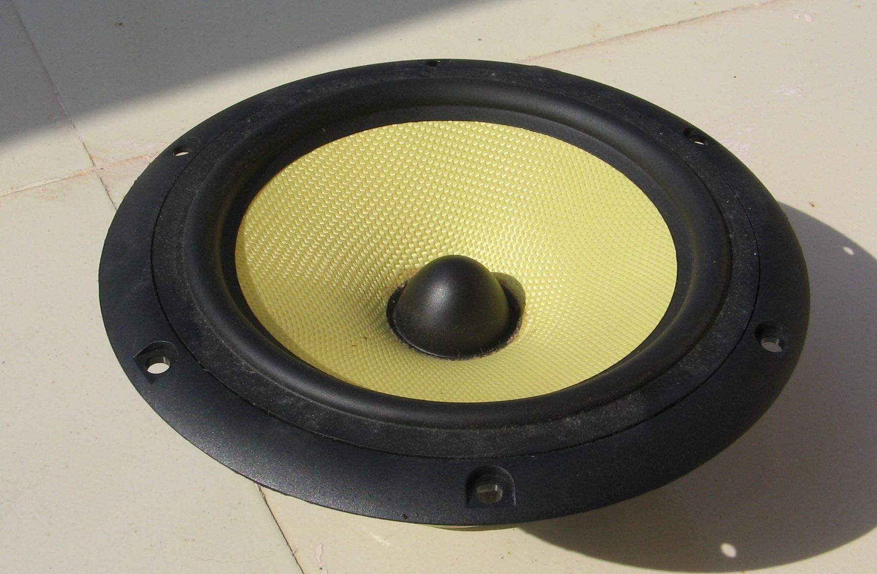
This Kevlar driver was finished like a jewel. I didn’t know whether it was technically well designed — I didn’t know enough about drivers to judge this. I could only see that this was no stamped-sheet-metal basket like the rest of the Peerless India drivers… it was a cast basket. I thought it was cast metal, but later realised it was some sort of jet-black polycarbonate material. The cone had a soft rubber surround and a black raised dust cap. The magnet was of average size. The flange was designed for surface mounting, not recessed fitting, and the edge of the flange tapered to a knife-edge so sharp, uniform and free of burrs and unevenness that I was willing to caress its curves most obscenely then and there, had I been alone. Lust must have been popping out of my eye sockets.
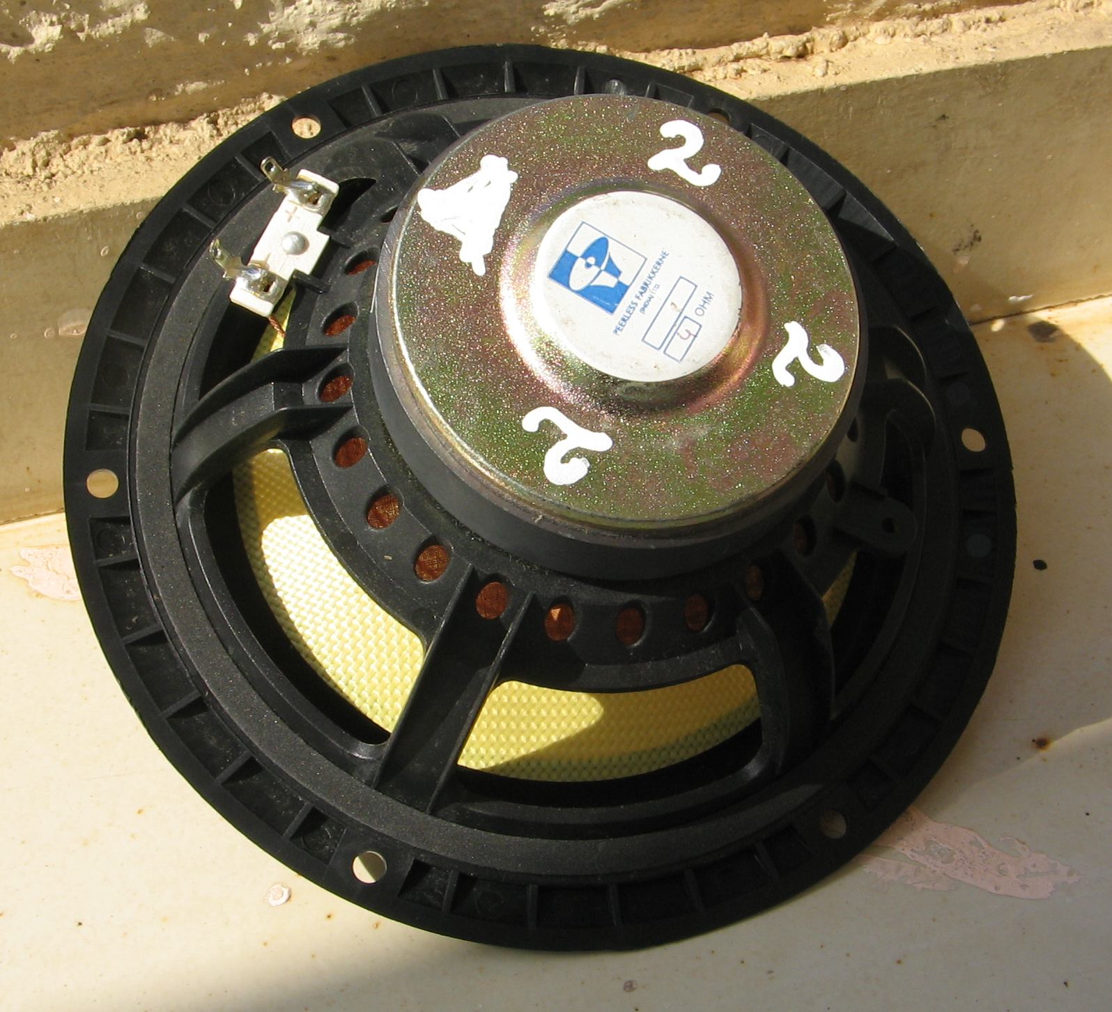
Jeetubhai had one page of data for each driver, in the form of a photocopy of a photocopy of a photocopy of a photocopy of some datasheet from somewhere. Most parts were as unreadable as ancient maps: I began to sympathise with Lara Croft, tomb raider. We saw the T/S parameters of the Kevlar driver and we could see that it had a stated Vas of about 36L and a Qts of about 0.34. It also had Fs of 36Hz, I think. (Later measurement of my samples turned out an Fs of about 42-44Hz.) All in all, a usable set of specs — none of that Qts of 0.9 nonsense which the Boltons had given me.
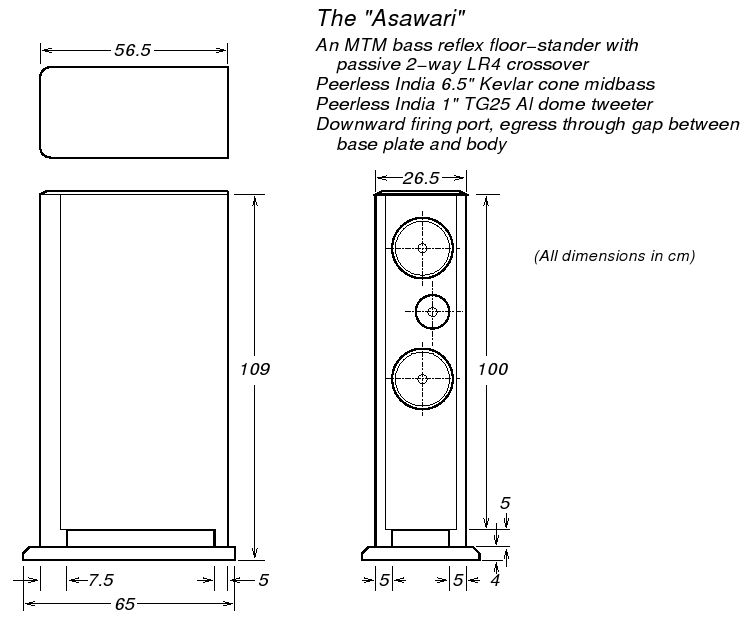
I decided then and there that I’d build my first pair of speakers using these Kevlar drivers and one of the good Indian tweeters. That’s what has finally become the Asawari. The tweeters I landed up using are called the TG25 Al-dome ones from Peerless India. Pretty conventional design without any top-end peak or harshness, ferrofluid-cooled, with an Fs of 1500Hz. Cost? The Kevlar cones were for Rs.1500 (about USD 33) each, and the TG25 were for Rs.800 (about USD 18) each. Prices have gone up about 10-15% since my purchase.
And I decided I would do an MTM simply to allow two bass drivers to handle the low frequencies. I thought this would make it easier to get low distortion and good SPL in the low regions; this proved very correct later. In fact, I have now begun to believe that plain TM architectures like the Proac Response 2.5 are an aberration: they can’t handle decent power levels cleanly unless the drivers have something exceptional about them. So you either design a simple TM standmounts specifically for low-SPL usage (some people just like their music clean but soft), or you go to an MTM or a proper 3-way.
Incidentally, we didn’t buy these drivers from Jeetubhai; he requested us to buy from one of his dealers. Since then, we have been dealing with Dilip Devyani of Dev Electronics, on the first floor of one of the antique buildings on Lamington Road. They can procure all the drivers Jeetubhai supplies.
The enclosure
I bought the Kevlar drivers and began figuring out how to take measurements so that I could design an enclosure for it. I wanted it to be a floorstander, because Angshu had told me that a standmount is a wasted optimisation anyway: a good standmount needs a stand, which finally eats up as much floor space as a floorstander. There is no real “bookshelf” speaker for high quality sound: only Bose Acoustimass speakers and Korean combo boomboxes can be kept on bookshelves without any worry about losing sound quality; they are too mediocre for their placement to make a difference.
So I knew I wanted an MTM floorstander. I began setting up Speaker Workshop to take impedance measurements. I read all the documents and tutorials and got thoroughly frightened reading about the Wallin Jig. Angshu told me to forget all about it and simply build a Claudio Negro impedance jig. I did, and I happily use it till today without a Wallin Jig in sight. I took all the impedance measurements in free air, got my trusted carpenter, Hiralal Sharma, to build a box for Vas measurements, and then measured the Vas. It may sound like all this took two days, but in fact it took more like two to three months. Things didn’t work initially. See my thread on Speaker Workshop forum and on diyaudio about the problems I faced and the path I had to take to get simple impedance measurements to work right. This was August 2005. A lot of this time went in building and understanding the impedance jig, and a lot also went in trying, then rejecting, the added-mass method of Vas measurement. It was only after all this that I got Hiralalji to build the Vas box for me, so that I could use the sealed-box measurement approach. It has a front baffle which doesn’t need to be screwed on… I just clamp it to the box using C clamps. I have a thick closed-cell-foam gasket all around the edge for air-tight sealing. This clamped-baffle idea is, as usual, from Angshu. It works beautifully; I’m on my third driver model’s Vas measurement by now.
Three of the four drivers had pretty consistent readings, but the last one was a bit out. Its Fs was almost 20% lower than the others. I checked with Angshu and decided to ignore it. Its Vas too was out by almost 20%. When the others gave me Vas readings of about 36L, this one reported 30L. I finally went with a Vas of 35L.
I began looking at various programs to do my box modelling based on the T/S parameters. The box modelling features of Speaker Workshop were okay, but didn’t seem too easy to use. I had read Vance Dickason 5/ed, and I was aware of the different alignments for a vented enclosure; SW seemed to support only a small subset of these. I tried WinISD, and found the graphic design of the UI off-putting. I tried Unibox, and loved it.
Unibox is amazing, because it eliminates the idea of vented enclosure alignments altogether. It re-visits the fundamental mathematics of Thiele, Small and others, and calculates the box response from first principles. The alignments like SBB4 and QB3 were shorthands methods designed by the early pioneers to make box design easier in the days when computers were not available by the six-pack. In today’s world, vented enclosure alignments seem to be an anachronism. So, I saw this first-principles approach in Unibox, liked the UI, and decided to stick with it.
I tried various box volumes, and discovered that if I select a volume larger than a certain upper limit and set a pretty low box tuning frequency (Fb), then the vented enclosure begins to resemble a large sealed box, but with better extension at the absolute low end (30Hz and below). Instead of a traditional maximally flat SPL curve followed by a clean knee and an 18dB/octave drop below that, I now got a slowly drooping curve, somewhat akin to a sealed enclosure with a Qtc of 0.6, followed by a knee, leading to a sharp drop in the graph. So, I could now create a model which would start dropping SPL from somewhere between 80-100Hz, and drop very gently till about 30-35Hz, after which the knee would come. From what I’d read, this gentle drop seemed the exact converse of room gain, so I thought it would be a great idea to build a box with this sort of unconventional alignment to offset the room gain and get relatively flat, very extended in-room bass. I had some doubts about all this, so I initiated a discussion on diyaudio about it, and got generally encouraging responses.
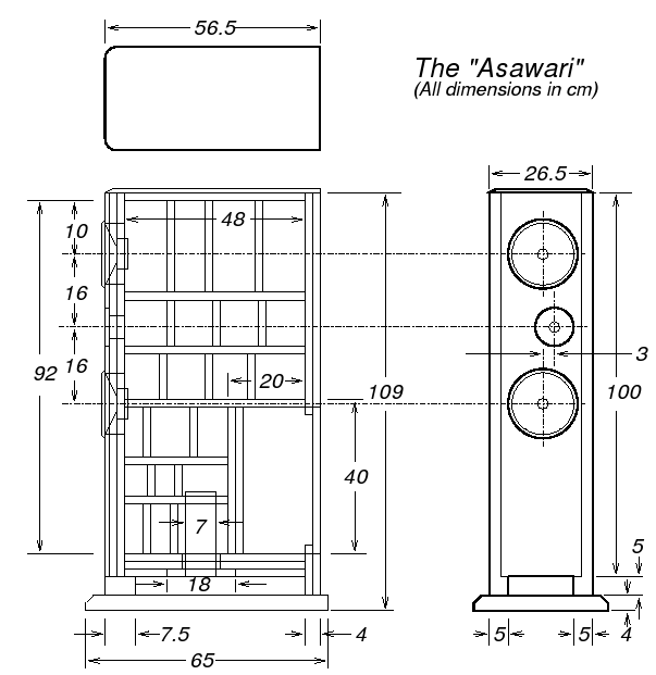
So, I went with a 60L enclosure volume for my pair of drivers. Now that the details of the volume were finalised, I had to decide on the actual dimensions and construction of the box.
One of the universally held beliefs about speaker enclosure construction is that they are made of MDF, just like apple pie is made, essentially, of apple. Some veterans talk of Baltic birch plywood, but they are a very select minority. My readings about what makes good enclosures, plus inputs from Angshu, convinced me that enclosure deadness was extremely important, perhaps more important than driver characteristics (within limits). Angshu in fact believes that most DIY enclosures radiate so much sound that their total radiation exceeds that from the driver at some frequencies.
So I decided that the choice of material alone would not fix the deadness problem; this needed much more effort. And if this sort of care was taken, then the choice of material would become secondary. So, to prove my theory, I decided that I would not use MDF for constructing the Asawari. I’d use good quality ply. And I’d use techniques of damping and vibration reduction fanatically, so that I’d get an enclosure deader than most DIY speakers (or commercial mid-fi speakers) built using MDF.
I decided to use 18-20mm marine plywood for the enclosure. This is less expensive than good MDF, and is available at all timber dealers in India. Marine plywood is better than commercial ply because it has little or no pores or airgaps — it’s simply better constructed. If you find A-grade commercial plywood, that’ll do too, I think, and will be about 20% cheaper than marine ply. And I designed an extensive structure of bracing, to emulate the matrix bracing that I had read about. Angshu had told me about matrix bracing — he said that B&W speakers are braced this way. He had used it for one of this small floorstanders and had got very good results. I also remember reading somewhere on Seigfried Linkwitz’ site that if bracing is applied in the form of a grid with grid sizes of about four inches, then the resonant frequency of the panel will be raised to single-digit kiloHertz levels. I decided to aim for something like that.
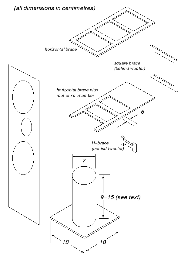
I used the same plywood for the bracing as for the outer walls. The matrix I designed resulted in rectangular patches of unbraced wall surface not more than about 8″x6″ between braces. And there were vertical and horizontal braces, all reinforcing each other. I used two sheets of ply for the front and rear baffles, and three sheets of ply for the bottom, just to allow a deep bottom plate to drive long screws in if needed. I used a single sheet of ply for the top surface, but fixed a 12mm thick sheet of float glass on it with Araldite, to make it a composite sheet. I have tried to draw the horizontal and vertical braces below. The horizontal braces have two cross-beams, and the vertical braces are rectangles, with a central rectangular cutout. Some of the smaller braces, behind the tweeter, are in the shape of fat capital-H, shown in the drawing as H-brace. These were too short to be made in rectangular shapes, hence the H.
Another thing I decided to do is keep a separate crossover chamber at the rear of the enclosure. Since this was my first pair of speakers, I wanted the full freedom to remove the covering panel for this chamber and pull out the crossover, without affecting the air-tight sealing of the acoustic chamber. On hindsight, I think this was a good decision. In the internal diagram, you can see this chamber, about 16cm deep and more than a foot tall.
I decided to play it safe with the volume calculation. So I built a spreadsheet with the volumes of each item, including the cone size and magnet size of each driver, the volume of each brace, and the volume of the corner columns (pure timber) which would eat up the internal space. Subtracting them from the gross internal volume, I arrived at the net internal volume. And I tweaked the depth and height to get the net internal volume as close to 60L as I could. I tweaked the height and depth in steps of +/- one centimetre, and arrived as close to my target as I could. I finally reached 60.7L. I froze the dimensions at that point.
The front baffle has rounded vertical edges, with a radius of 1″ (2.5cm). I built this by using wooden beams of 3″x2″ cross section, running the full height of the baffle on both sides. These beams were shaped as per the corner detail shown below, and one edge was rounded. In the diagram you can see how I am using two sheets of thick ply plus one sheet of 3mm ply plus one sheet of 4mm veneer for the front baffle, and one sheet of thick ply plus one sheet of 4mm veneer for the side walls. The extra addition of the sheet of 3mm ply on the front baffle is for recessing. The tweeter needs to be flush mounted, and I decided that it would be easier to do the recessing by cutting the smaller mounting hole in the thick ply sheets, and the wider flange-fit hole in the 3+4mm of ply+veneer. That way, I got about 7mm of recessing, which was sufficient for the gasket seal plus the thickness of the tweeter flange. I thought this was a smart way to do flush-mounting and was patting myself on the back, but I later saw that Roman had documented it on his Website.
My carpenter Hiralalji began work based on the drawings I gave him. He made the basic box quite quickly with the side walls, top and bottom, and then began working on the “partitions” as he called them — he meant the bracing. These braces took a lot of time because he had to cut each one precisely to fit tightly inside the shell, and also had to cut out the central portion to make a large hole in the middle of each brace. All in all, he must have worked, with a helper, for a month, to complete the pair of enclosures and cover them with veneer sheet.
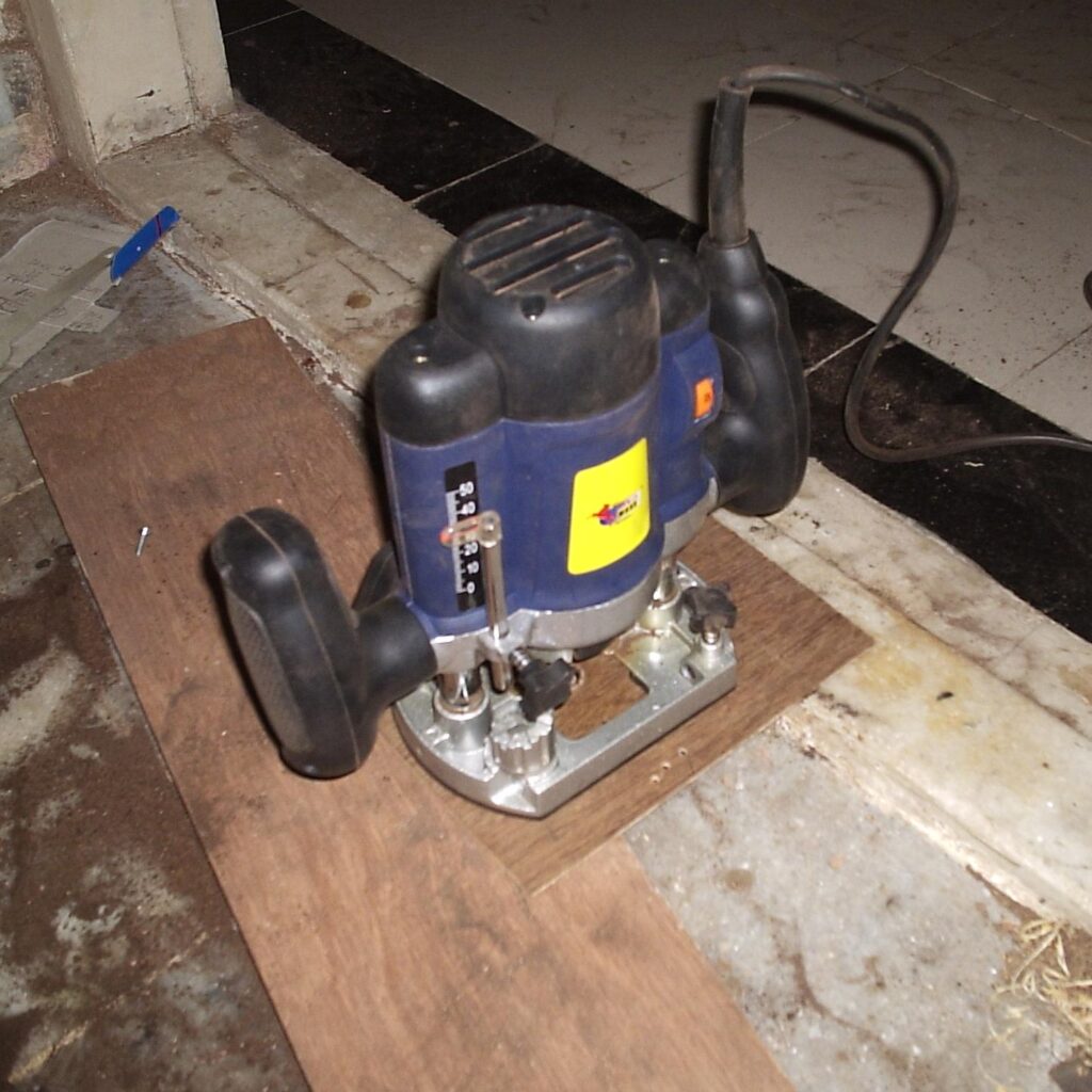
This was an interesting project for him because he saw a router for the first time. (This applies to me too in fact.) I bought an inexpensive PowerMaxx router from Lohar Chawl for him to use. He spent half a day just inspecting it, fitting a bit into it, and trying to make test cuts. After that, he gave it his seal of approval and said it was a lovely way to cut circles. The router cost me about Rs.1800 (about USD 40.00) and each router bit cost about Rs.150 (USD 3.00). These bits keep breaking after every few days of heavy use.
The enclosures finally got done sometime in December, and then I got them polished using a melamine polish. This is a thin waterproof treatment, where the last melamine coat is sprayed on using a spray-paint setup. Hiralalji charged me Rs.8000 (about USD 160) as just labour charges for the carpentry work, and the polishing chap took Rs.2500 (about USD 50) for the labour and material of the polishing. In addition, the cost of plywood, veneer sheets, and adhesives exceeds Rs.14,000 (almost USD 300).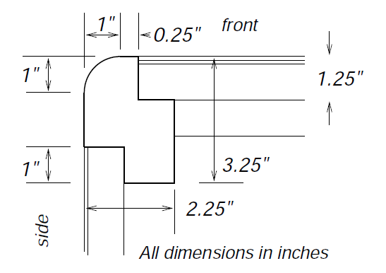
I then added Dacron lining on all the internal surfaces. I smeared Fevicol with my fingers all over the internal walls and on all surfaces of all braces. I then took a pillow filled with Reliance Recron — that’s their name for Dacron, I believe — cut it open, and pulled out the stuffing from it. I slapped on about one to one-and-a-half inches of this silky-smooth white fibre on all these internal surfaces; it seems to hold well with Fevicol. In case you are wondering whether this Recron is different from normal cotton-wool, lay your mind at rest: it is. It feels totally different. Recron feels sort of slippery and synthetic like polyester, and is lighter, silkier, and fluffier than even good cotton. The audible effect of this difference is of course something I can’t comment on. Why did I use Recron instead of ordinary wool? Because people on the forums keep talking about using Dacron, and no one talks about using cotton. This could simply be because they get Dacron more easily than good cotton in most Western countries, I don’t know. рџ™‚
Once this was done, I fixed the drivers on the enclosure using closed-cell foam sheets as gaskets, wired them up internally, brought the leads out into the crossover chamber, and began thinking of SPL measurements in preparation for crossover design. I used multi-strand copper wire of the kind electricians use for wiring up all the equipment in medium-sized offices. My electrical cable for internal speaker wiring had an effective cross-section area of 6 sq-mm, which translates roughly to as much copper as solid-core 9-10 AWG wire, I think. This sort of single-conductor multi-strand copper wire cost me about Rs.40 (about USD 1.00) per metre; I purchased it from my neighbourhood electrical supply shop.
Below are some photos of the construction process. These photos show the enclosure with top, bottom and side walls, and the braces partly in place. The vertical beams on the two sides of the front baffle are clearly visible, though the front baffle itself has not been fixed yet. Can you see the “H” shaped cross-braces behind the place where the tweeter will fit?
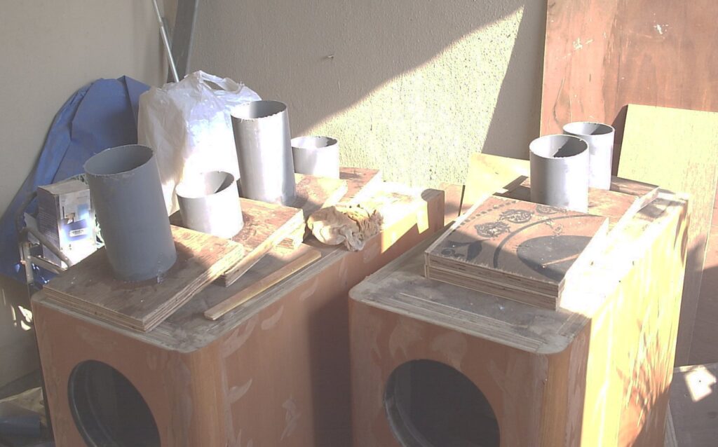
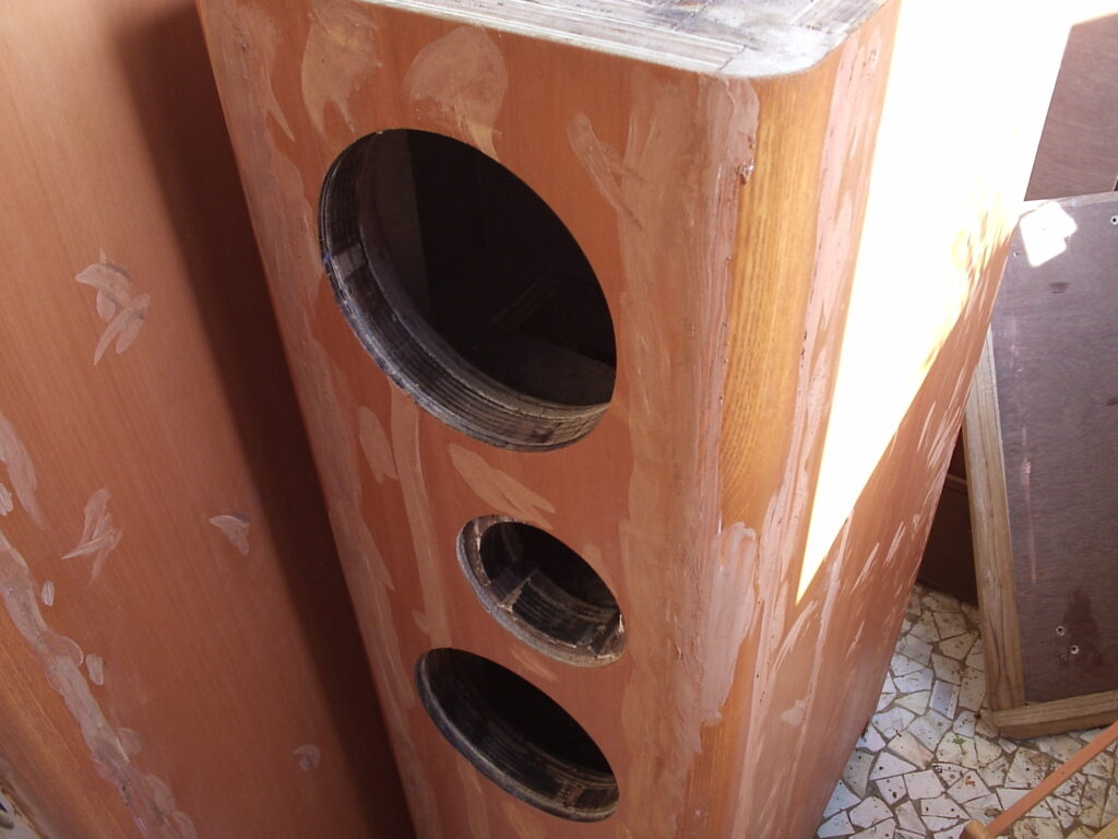
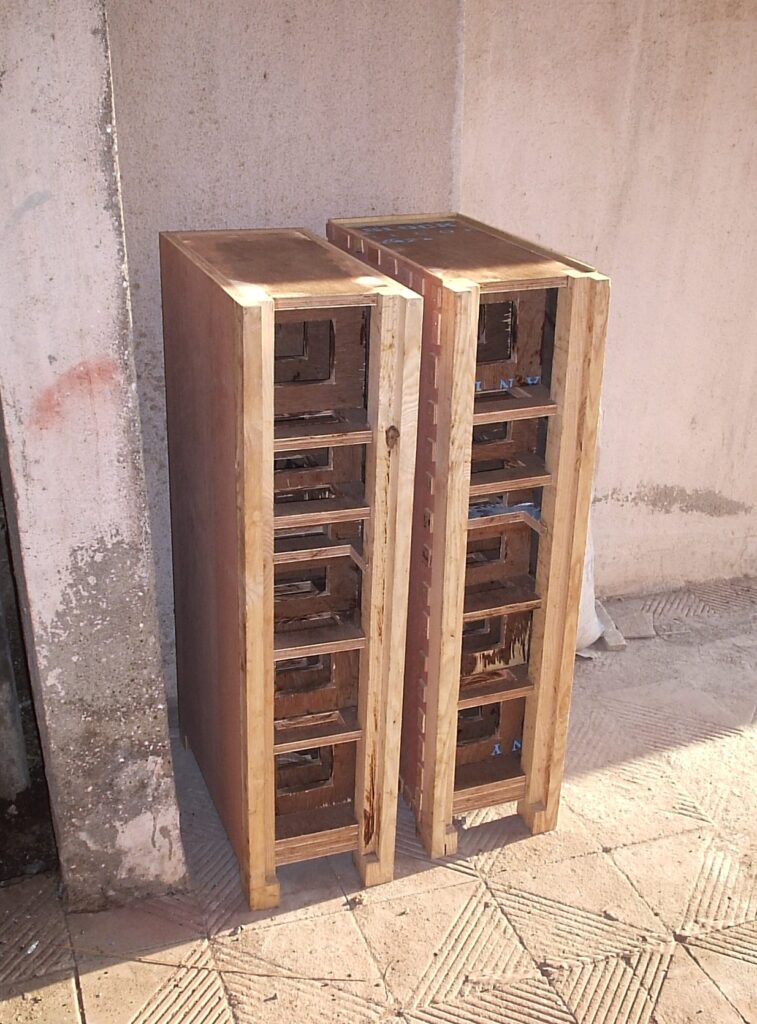
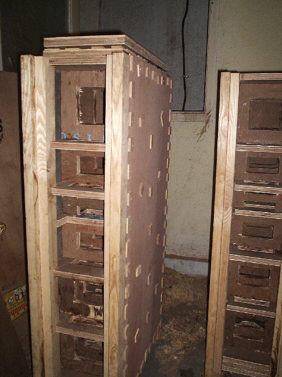
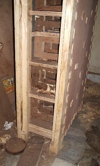
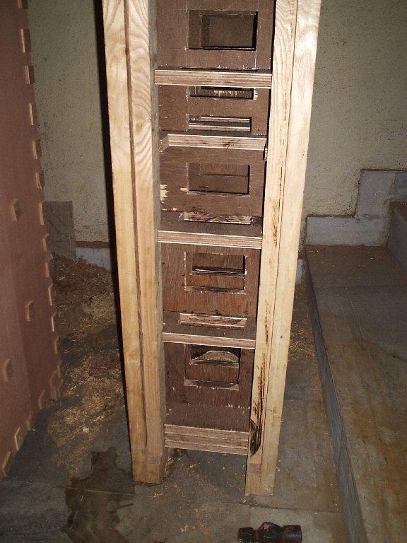
In the set, there is a well-lit view of the boxes under construction, and a shot of the boxes with the front baffles in place and the vertical edges rounded. In the open-box shot, you can see the triple-thickness bottom, single-sheet top, and the way the vertical beams for the front baffle have been shaped with grooves to fit the double-thickness front baffle. The grooving which Hiralalji used for the front baffle is a bit different from what I had drawn in the corner detail above. He decided not to keep the two sheets of the same width; the inner sheet is two inches narrower than the outer one. And in the next shot, you can clearly see the final appearance emerging from the woodwork.
In the next set, you can see the router I bought from Lohar Chawl, and the pile of interchangeable ports I decided to make. I made three pairs of ports, with lengths ranging from 11cm to 17cm. Each port is fixed to a square sheet of plywood, and I can swap ports by removing four screws. Since these ports fire downwards, they are invisible and not finely finished or veneered. I really love the idea of a removable port, and I’ll probably use it on all future bass reflex constructions. I also got two square pieces of ply cut of exactly the same size as the rest, to allow me to convert the box to a sealed enclosure if I wanted to.
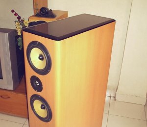
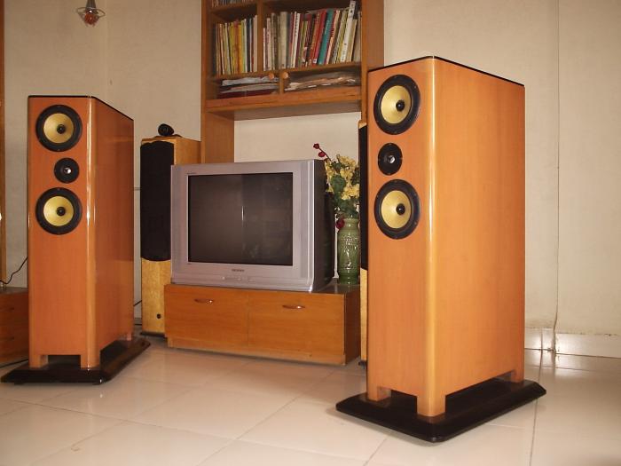
And here is the finished pair in the living room, with the old Wharfedales behind them. The Asawaris look well finished, but have a fairly boxy shape, due to almost two feet of front-to-back depth. The two inches of gap between the enclosure and the base board are clearly visible: this gap is open on the front and sides, and closed at the back. The 12mm glass sheet as the top plate looks quite smart, I thought, and also makes for a wear-resistant and usable table top.
The crossover
The enclosure was now ready, including surface finishing, the drivers had been fitted, and the internal wiring of the drivers had been done and sealed with Araldite, leading out to the crossover chamber. Now was the time to take SPL measurements and stare at the curves, in preparation for the crossover design ordeal. I have great faith in the creative potential of staring at curves. Look inside the brain of any mathematician studying obscure journals, or inside what goes in lieu of a brain in a schoolboy staring at curves of topless sunbathers, and you’ll see all sorts of creative surges passing through the brains. Curves do that to you, and I was all set to do some serious staring.
I had already taken impedance measurements of individual drivers. From that data, I had seen the low Re (3.6 Ohms) of the Kevlar midbass units, and so I had decided to wire them in series instead of parallel. The TG25 tweeter was a healthy 5.6 Ohms or so, IIRC.
How long does it take someone to take SPL readings of one pair of midbass units, and one tweeter, when one has SW working with one’s computer and has a Panasonic mic capsule which has been tested in test recordings before? Half a day? One day?
It took me much longer. It felt like much, much longer than it took.
First of all, my SPL readings just wouldn’t work. This was October 2005, before the Asawari cabinets were built. I was trying them on the factory-bought speakers I have, not on any DIY drivers. I was expecting a flattish line from about 200Hz to 20KHz (won’t go below about 200Hz with the MLS time interval I can use in my living room). But I got strange things. If I used a sampling rate of 24KHz, I got a strange rolled-off curve. If I used higher sampling rates (as I must, to take accurate readings of the tweeter), I got no MLS spike at all. I posted on the Speaker Workshop forum and on diyaudio. I was totally stumped (I would become intimately familiar with this feeling of stumpedness over the next few months). I was trying the same things over and over, night after night, changing various settings, cleaning RCA jacks, playing with signal levels, testing sine wave readings (which always worked beautifully), and generally alternately cursing and praying. Guys on the forum were generally trying to help, and one of the members on diyaudio actually gave me a clear pointer to the cause of the problem, but because of my indisciplined debugging style, I missed it completely. I was wondering whether SPL measurements are at all possible with a USB-connected external sound card. I was wondering whether my investment in this sound card, imported from S’pore with great trouble, was now going to be a waste.
This is the problem that Angshu walked me through, I’ve referred to this story elsewhere. He was in Bombay that night, on one of his short, hectic official visits. He was as clueless about the specific cause of my problem as I was, but he had years of experience in debugging SW problems. So, at ten in the night, sitting in a hotel room in South Bombay after a long day’s work, he started speaking with me on the phone, and walked me through a long two-hour process. We got it working in the end; it was past midnight. I can only imagine how tired he must’ve been.
The problem was with the way various sampling rates are implemented in Creative Soundblasters. This family of cards implements hardware sampling rates of multiples of 12KHz only. Other sampling rates are derived from these by resampling. This means that there’s hardware-level sampling implemented for 12KHz, 24KHz, and 48KHz. For 44.1KHz, it’s read at 48KHz and resampled. In my crazy, non-systematic style of debugging, I had not realised that 44.1KHz is failing but 48KHz is working. So I had concluded that “high sampling rates” are not working. There was also a problem of level setting — my levels were sometimes too low.
Angshu made me disconnect the mic, and just put a loopback cable on the sound card, and measure the sound card’s impulse response, not SPL graph. I have now realised that this measurement of impulse instead of SPL is a life-saver. It has gotten me out of jams many times later. When I did impulse measurements, I was getting clean spikes at 24KHz, but none at 44.1KHz. He also helped me set the gains to ensure I was getting a tall enough spike at 24KHz. I then tried 48KHz and, with the right gain settings, I got the spike!! I still remember the feeling of relief which swept through me, dog-tired, depressed, and sweating, that midnight. And Angshu must’ve silently sent a thanks-giving prayer, knowing he would now be able to get rid of this pain in the neck and go to bed.
I then switched to SPL readings in loopback mode, and saw the sound card’s SPL curve coming out neat and flat. Then I disconnected the loopback cable, switched over to the mic, and took some actual SPL readings. They worked. I almost couldn’t believe my eyes. They’ve worked ever since.
The critical things are
- With a Soundblaster, make sure you use sampling rates of either 48KHz or 96KHz. Lower than 48KHz are anyway no use for SPL readings for xo design purposes. And other sampling rates like 44.1 and 22.05KHz work for all other kinds of signal shapes, but not for MLS spikes.
- Use appropriate recorded signal levels. Your impulse reading must show peaks of at least 500 (on a scale of -32000 to +32000, for a 16-bit digital resolution). Yes, the number is 500, not 5000. I never got MLS spikes more than 10000, though sine waves can easily be recorded at full resolution (+/-20,000 or more).
- It’s always a very good idea to use a loopback cable and measure the FR curve of your soundcard using a package other than SW. I recommend Rightmark Audio Analyser strongly. This graph will tell you whether the high sampling rates are working and the upper end of the sound card’s response is flat enough. What if you have a card for instance whic supports 96KHz sampling rate but always rolls off the upper end after about 25KHz with an analog filter? RMAA will show up all this, without you having to go through the pain and frustration of having to learn to use SW.
Some people want to know: is this sort of USB-connected external Creative Soundblaster really usable for speaker design, with all its problems? My answer is a resounding “yes”, once you know how to work around the problems. These cards are inexpensive, reliable, and the newer versions give you 96KHz sampling rates. Some (the Audigy) even give you 6 or 8 channels, allowing you to test out crossovers in real time using digital simulators available with SoundEasy or LspCAD. I have seen first-time DIY builders investing in really expensive professional sound cards, and I’ve always wondered why. I still wonder, sometimes. рџ™‚
Then I experienced another glorious glow of stumpedness when I tried taking SPL measurements of the finished Asawari a few months later. My SPL graphs showed strange jagged edges which I couldn’t eliminate, try as hard as I might. Desperate, I fell back on impulse measurements, and found that I was getting a small spike just before the first room reflection from the floor. This small spike was really screwing up the SPL curves. After a lot of heartburn and head-scratching, I decided to try fixing the mic on my tripod without the wooden jig I had built, and Viola! (or whatever it is that they say in your part of the world) the problem disappeared.
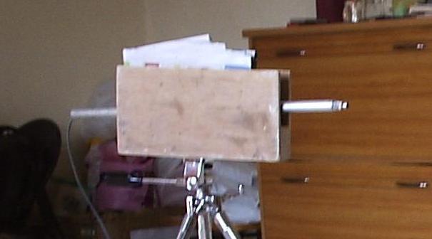
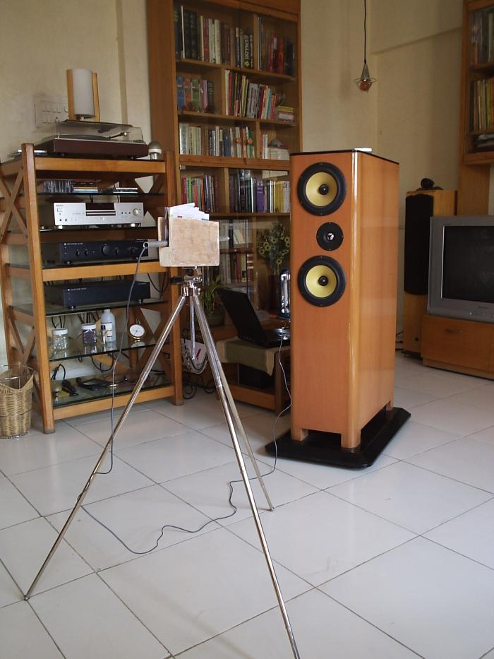
A word of explanation here. I had fixed my Panasonic mic capsule and mic cable to a quarter-inch aluminium tube, and the mic was potruding out one end of the tube, fixed in place with cellotape. So I had an aluminium wand for the mic, smooth and light for easy measurements. I had then built a wooden jig with a nut at the bottom, into which I could stick this wand. The nut of the jig allowed me to fix it to a camera tripod.
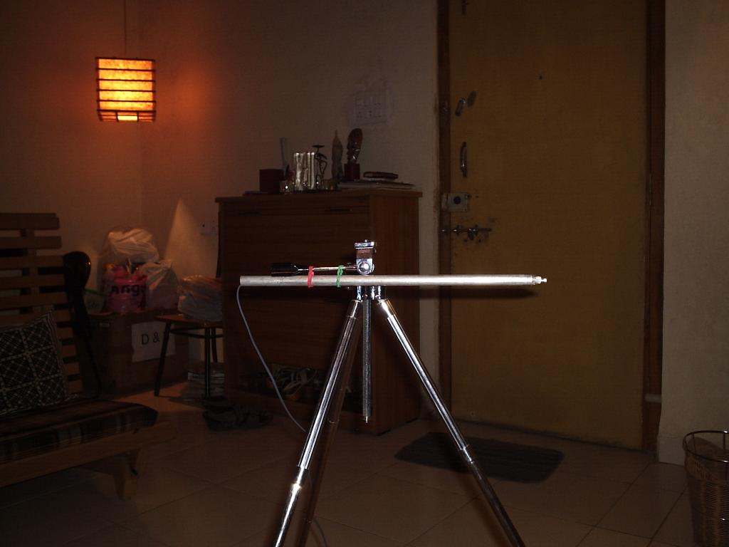
I discovered that if I dropped the wooden jig and used string to tie the wand directly to the camera tripod, the preliminary reflection spike disappeared from the pulse measurements. The photo on the right shows the wand fixed with two rubber bands to the ballhead’s handle on the tripod. It’s only after you try taking accurate measurements that you realise how problems come from unexpected quarters. Vance Dickason didn’t tell you nothin’ about nothin’.
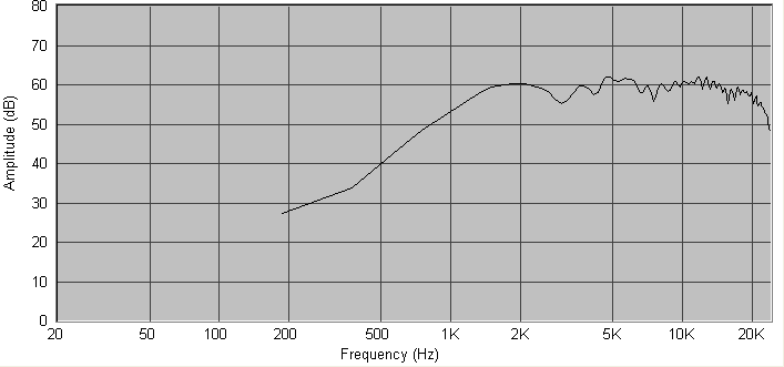
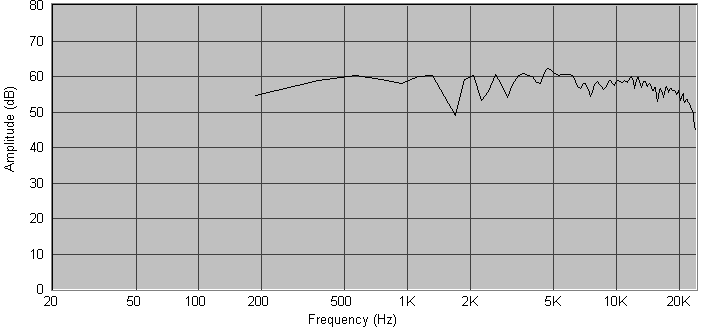
Once this hurdle was crossed, I took measurements of both the midbass and tweeters, and tried building a crossover with them. This was the tweeter curve I got:
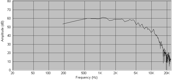
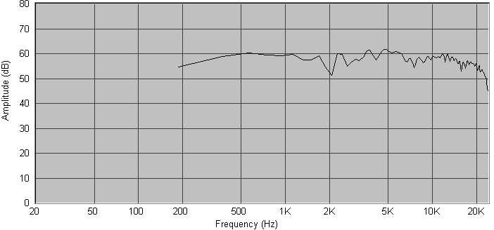
And this was the midbass units’ SPL, both drivers in series:
I used SW’s built-in stock crossover insertion feature to insert fourth-order crossover components and used the optimisation feature to get them to align to precise low-pass and high-pass goals. Anyone who has used SW or any other speaker design and modelling package will know what I’m talking about. Angshu had predicted that I’d get the crossover done in an hour once the SPL measurements were in place, and indeed, I now had a crossover schematic in place, which seemed to be giving me nice individual rolled-off curves for the woofer and tweeter:
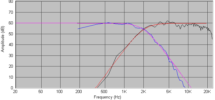
When one combines the woofer’s graph with the tweeter’s, one should get a flat SPL curve for the total speaker. I tried combining my graphs and landed up with a curve which was quite okay at the ends, but had strange jagged edges stretching for about one octave on either side of Fc, with peak-to-trough heights of 8dB or more:
When one reverses the polarity of one driver and combines the two graphs, one expects to get a deep notch of perhaps 20dB or more at Fc. I tried reverse-combining, and I got no notch at all. I just got jagged peaks and troughs just like the straight-combined graph:
At the risk of sounding repetitive, I was totally stumped. There was nothing in the books about this.
I asked on the forum — the records show 15 May 2006. I got all sorts of answers, many of them helpful. Here I first encountered one of the basic concepts of crossover design: minimum phase. This term was to haunt me for quite some time after that, and is still haunting me, as I explore three-way crossover design. Friends on the forum patiently walked me through the phase related issues, but couldn’t fix the problem. Then John Krutke of Zaphaudio fame, a seasoned designer, pointed me to Roman Bednarek.
Roman was a turning point in my quest to understand crossover design. His approach was quite different from Angshu’s. Angshu designs crossovers by plugging in stock crossover topologies in SW, and then asking SW to optimise the values to get precise curves. When things go right, Angshu can arrive at a pretty usable crossover topology in an hour. Roman builds topologies “by hand”, by adding one component at a time, watching each component’s effect on the SPL and phase curves. He says he rarely uses the optimiser. He hand-tunes both the topologies and the component values of individual coils and caps to get the curve just where he wants it. And Roman is a veteran user of SW. I don’t think Roman’s approach or Angshu’s approach produces better-sounding speakers, but Roman’s approach probably allows him to fix troublesome situations better. Like mine. There were others on the forum who too advised me to start serious hand-tweaking: see this post for instance. This advice was teaching me a totally new way of looking at crossover tuning.
In parallel with my discussions with Roman, I continued to take inputs from members on the forum, and in three days, I had fixed the jagged-graph problem. The cause was my sound card. My sound card, the Creative Soundblaster Digital Music MP3+ USB, has randomly varying latency. This means that when the computer generates a pulse signal out of the sound card, the pulse will sometimes emerge in half a millisecond, sometimes after a delay of three milliseconds, sometimes after five. This delay is called latency, and latency is not a problem per se, but randomly variable latency of my kind certainly is. What had happened with my SPL readings of midbass and tweeter is that the two SPL readings had been recorded with two completely different latencies — it was as if I had shifted the mic position between the readings. As a result, the two readings were totally out of phase, to a random degree. Hence, when combined, the midbass and tweeter graph were showing me a badly out-of-phase, interfering summing signal. Such out-of-phase signals will sum with a jagged graph.
I learned how to take multiple phase-coherent readings with my sound card. It is a workaround, and this is something most people with more stable hardware don’t know about. No wonder Angshu couldn’t fathom the cause of my problem: he’s never worked with such “creative” sound cards, the poor deprived soul that he is.
So now I knew how to take phase-coherent SPL readings, and also to use the “Remove Excess Delay” function of SW to make the phase curve readable and meaningful. (Roman actually guided me a lot here, writing long, lucid emails patiently.) And I now had a summing SPL curve where the midbass and tweeter summed nicely without any jagged edges. I still have all his emails.
But I still didn’t have the reverse null of 20dB — I was getting a null of 8dB or less. I looked deeper, again with the help of friends on the forum and Roman. And discovered this was because at the Fc, the midbass was not in phase with the tweeter: there was a small but significant phase difference. That’s when I learned one of the important limitations of the automatic slope optimiser: they optimise only the SPL, not the phase.
So I started hand-tweaking the component values to try to get the phases of the midbass and tweeter to align. And struggle as I might, they didn’t align. When I got the phase right, the SPL was way out of league. When I got the SPL right, the phase was out by dozens of degrees. I turned to Roman and Angshu for help.
Roman designed my crossover for me.
He told me to forget the 2KHz Fc that I was aiming for: he thought it would be too low for the tweeter I was using. He designed a crossover at 2.8KHz, perfectly phase coherent and with a fairly flat SPL. I had sent him my SPL curves in a .SWD file, and he sent me a ready-to-use crossover back in the same file.
I looked at this crossover and realised I could never have arrived at it using Angshu’s plug-and-play auto-optimised technique. Roman uses resistors in series with shunt caps or shunt coils to control the curve at the “knee” of the crossover, and also uses a large entry-level coil on the woofer’s low-pass crossover to handle the baffle-step compensation problem. Now both Angshu and I are studying all the crossovers Roman has published on his Website for his projects. They’re very interesting.
Another valuable insight I gained from all this was asymmetric slopes. Till then, I had naively assumed that when two signals are being summed to get a flat sum, the degree of “negative slope” in one signal should equal the “positive slope” in the other. This assumption stemmed from some sort of basic belief in the symmetry of complementary forces. So, if the low-pass filter was giving me a 24dB/octave slope at and beyond the Fc, the high-pass must also have a 24dB/octave slope, if I had even a remote chance of getting a flat sum. Right? No, not necessarily.
It is perfectly possible to get a flat sum by combining a third-order low-pass with a second or fourth-order high-pass. Nothing magical about it. When I thought more about it, I realised that any experienced speaker designer would know this, but if one just assumed things based on engineering intuition, one might miss this point. And this insight is key to getting phase and SPL to align in troublesome crossovers. Crossover designers often use asymmetric slopes at the Fc in order to tackle phase mismatches, I discovered.
I decided to just go ahead and build what Roman had given. And this crossover remains the one in the Asawari, apart from the one contribution I was to make: tweeter level tuning.
Crossover tuning
I had a ready-made crossover design now, and I was all ready to see the finished speaker singing for me in a week’s time. I had thought that’s the amount of time it would take to get parts from Corrson — I’d dealt with them before, they are prompt and professional.
I sent them the list of parts. They said they didn’t have some of the resistor values I wanted, so I decided to go with local Lamington Road white-coffin resistors instead. They also said they couldn’t make microHenry coils — I’d asked for a 220uH. So I went looking for someone in Lamington Road who could make a coil for me. I just didn’t have the enthusiasm to wind my own coil if I could pay someone to make it for me.
So, bidding goodbye to my dream of seeing the Asawari sing in a week, I went trudging through the crowd and noise of Lamington Road, to this firm on the second floor of one of those ancient wooden-staircase buildings. This firm was Disco Winding Works; they make transformers to order, besides other things. I tried telling them about making a pair of coils for me. They had all the enamelled copper cable in various gauges, but didn’t have suitable jigs to set up a bobbin and make a coil. (When all you Westerners blithely order coils from Parts Express or Madisound, I want you to remember this story. рџ™‚ ) So I persuaded them to think of some way out, and the owner said he probably could rustle up something for me. Would a plastic bobbin do? He showed me the bobbin: it was two inches wide along its axis, made of white plastic, and had the words “Johnson & Johnson” clearly marked on it — it had held bandages from the medical company at some point. I said it would do. The owner then asked me, very politely, could I tell him how many turns this 220uF would take? I went home, went online, used some coil calculators, calculated the number of turns for a 2″ coil, and emailed it to him. Four days later, the coils were ready. They cost me Rs.700 (about USD 15.00). They were made out of 16 SWG copper, which is like 14 AWG for Americans. Angshu says I am fool to have got coils made by someone at this price — he is probably right. I was simply tired.
Angshu suggested that I check whether Corrson can make 0.22mH coils; I shouldn’t mention micro-Henry. I found the idea ridiculous — does this mean Corrson does not know the relationship between milli and micro? Well, I did ask. And guess what? Corrson said “Sure, we can make 0.22mH coils.” I felt like such a fool for not having checked with them before. And Gooroo Angshoo had won once again. рџ™‚
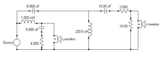
The rest of the components (large metallised polypropylene capacitors mostly) arrived from Corrson bang on time, and I fished out an unused pair of 1.5mH coils I had lying around. 10 W resistors of the requisite value came from Visha Electronics on Lamington Road. I put the crossover together, cursing the soldering headache of the huge, fat copper junction points where half a dozen 10 AWG wires met at the negative points of the crossovers. These are the points where one wire goes to the negative terminal of the driver, one to the negative terminal of the speaker input, and one each of the terminals of assorted coils, resistors and what have you. They can get as fat as an average-sized thumb. I hadn’t seen Troels Gravesen’s site by that time, or else I’d have picked up his idea of using lovely solder tags for crossover soldering.
Finally, the crossovers were ready, one Sunday morning. I hooked up my amp, turned the volume low, and played something, checking for screeches, smoke or anything else. Nothing. The sound was “normal”. It was working. I spent the whole of that day just playing CD after CD, at fairly high volumes. There was no instability, crackling, or strange noise anywhere. The speakers were behaving themselves, on the whole. The enclosure was as dead as I had hoped it would be. My gamble of plywood over MDF had paid off well.
But over the next few days, I began to feel that the sound was way too sharp. Angshu came over on one of his visits from Delhi, and heard the speakers. He admired the appearance and was impressed by the deadness of the enclosures, but he too finally shook his head about the brightness and harshness. Everything was sounding way too analytical, cold, and bright. When I say everything, I really mean everything, including voices of Harry Bellafonte or Mark Knopfler, not just guitars and cymbals.
Angshu was worried. He told me to take SPL readings as soon as I could. He said that if I could find any anomaly in the SPL curve, it could be fixed by either debugging the crossover or tweaking it. But if the SPL curve showed up a straight, predictable curve, and the harshness persisted, I might be in deep trouble, because there would be no obvious problem to fix. He also wondered whether this harshness was because of my using plywood instead of MDF — maybe there were cabinet vibrations at frequencies we couldn’t detect with our finger tips.
I took SPL readings. Nothing wrong; it matched the modelled SPL curve within half a dB. We were at a loss.
Totally clueless, I decided to try some messing around instead of twiddling my thumbs. In the crossover schematic, there was a 15 Ohm shunt resistor. I wondered what would happen if I reduced that to a lower value, so that the tweeter level would be cut? I modelled the change in SW, and I could see how the band from 3KHz and beyond would be pulled down by a dB or two, without affecting the phase coherence at Fc. So I decided to add a 33 Ohm resistor in parallel with the 15 Ohm. It was magic: the sound cleaned out and vocals became very listenable. I knew I was onto something.
I replaced the 33 Ohm resistor with a 22 Ohm. The sharpness became even more subdued as expected, but it began to appear a bit dull now — I didn’t like it. So I now had a range to play in. I pulled out the 22 Ohm and put back the 33 Ohm. Back to the old sparkling but listenable sound. I left the system this way for a week, playing music for an hour or two, ranging from Pink Floyd to Dire Straits to Diana Krall to Patricia Barber to B B King to Chet Atkins to Rashid Khan to Shahid Parvez to Kishore Kumar. I just soaked in the sound. More on the sound in the next section — let me complete the crossover story first. рџ™‚
After a week, I decided that some bits of some songs were still sounding really bright. The James Bond 007 album had two lovely songs by Shirley Bassey: they sounded too bright. In “Private Investigations” from “Love over Gold”, there were a couple of points where the guitar and drums broke out into a crescendo, with very sharp transients. Those passages seemed over-sharp, almost as if glass was shattering. I decided that a good speaker should keep these bits within the limits of listenability. I decided to add a 150 Ohm resistor in parallel with the 33 Ohm which was in parallel with the original 15 Ohm.
It helped. I continued to listen for a couple of weeks more, and I was happy. Even voices seemed to become just that bit smoother and cleaner. My friends, who had wanted to buy the Asawari from me, came and listened for a couple of hours. They were thrilled. My wife gave the sound her stamp of approval. And that’s where the crossover has remained till now, and probably where it’ll remain till the Asawari moves to her new home in Goregaon East, where my friends live.
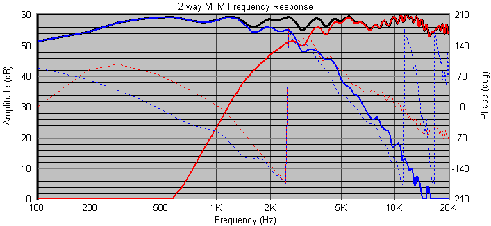
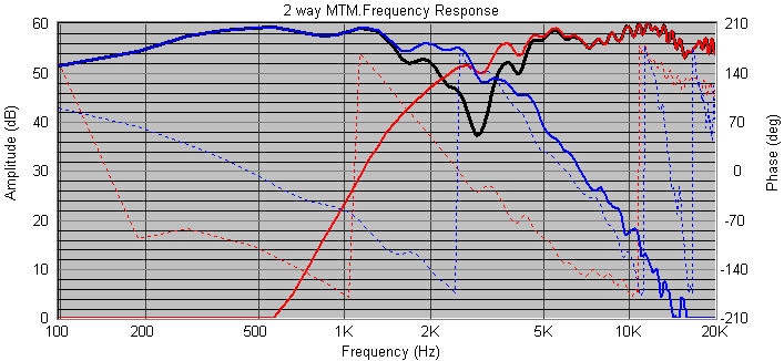
I took measurements of the speakers, on axis, first with just the original 15 Ohm, then with the 33 Ohm added, and then with the 22 Ohm in place of the 33 Ohm:
The graphs clearly showed the effects of the resistors. But some of my speaker-building friends were skeptical about the effects of such small tweaks: each step was a drop of just 0.5dB to 1.0dB in the tweeter level. One friend in fact flatly refused to believe anyone could hear such small differences — he stated, “You can’t hear differences less than 3dB, it’s been scientifically proven.” I didn’t want to argue with him, but I could see how that 3dB figure from those lab tests was out of context here. If you generate, say, a 400Hz test tone in a lab environment, and ask listeners to identify a change in volume, they will probably notice volume changes only in steps of about 3dB. But if you change the level of one part of the spectrum with respect to another part, and play full-spectrum music on the system, then this relative tilt in the spectral balance is detected as a change in the tonal characteristics of the sound, not a change in volume. And such tonal changes can be detected very easily even with a 1dB tilt — you don’t have to go up to 3dB for this. I didn’t get into an argument on this issue, but I retained my shunt resistors. рџ™‚
So now I know that tweeter level tweaking alone can change the sound of a speaker from intolerably bright to lovely, in some cases. My original crossover schematic had a 15 Ohm resistor across the tweeter; my fine-tuned one has something like 10 Ohms there. If I were to build from scratch again today, this is what I’d start with. I wrote to Roman about this — it’s his crossover design after all. He said my observations made sense, though he was a bit skeptical about the audibility of that last 150 Ohm tweaking I’d done.
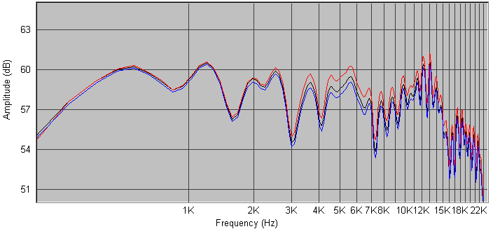
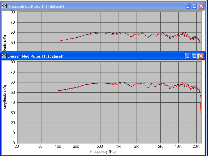
I took measurements of the speakers, on axis after the tweaks. The two graphs are for the two enclosures, and the two lines in each graph are the modelled and measured SPL.
The sound
It sounds great, as all DIY system builders know. Their latest speakers sound the best in the world. рџ™‚
I have a pair of Wharfedale floorstanders, which were my main speakers till now. I also have a pair of simple full-range standmounts with Jordan JX92S drivers. I’ll try comparing the Asawari’s sound with these, and with my (unreliable) memories of other speakers I’ve heard.
Tonal characteristics: The Asawari does not have the smooth, valve-like sound of some speakers I’ve heard. I recently heard some Gamut speakers, which retail for $13,000 a pair, and which use the Scanspeak slit-paper-cone midbass units which retail for more than USD 200 each. Those have that ultra-smooth valve-like sound. I guess this difference is due partly to the cone material: Kevlar will not sound like paper cones. It could also be partly due to the distortion reduction measures in the Revelator drivers which Scanspeak is famous for.
Otherwise, the Asawari has a very balanced tonal nature; you can listen for hours on end. If your amp is particularly bright, then the Asawari may sound too bright for extended listening. With my five-year-old Cambridge Audio amp, it sound quite right. My friend (the new owner of the Asawari) has just purchased a Cambridge Audio 640 v2 integrated amp, and dumped it at my place. That seems to create a bit brighter sound on the brightest of albums. Voices sound very real and clean on both amps.
The Jordans have a tonal balance for voices which is in a league by itself. I guess I’ll need to be a much more skilled crossover designer, and use better drivers, to get that level of subtle, smooth and real tonal balance from my speakers. However, once one steps out of the zone of voices into the zone of orchestral music, the Jordans have neither the bass nor the clean highs of the Asawari.
One of the major contributors to the Asawari’s lovely tonal balance is undoubtedly the BSC built into the crossover. Thanks, Roman. That 1.5mH inductor on the low-pass filter does most of the trick, I believe.
Detailing: The Asawari is much more detailed than the Wharfedales. The enclosures of the Wharfedales almost sing at high volume levels, and the Asawari has really dead enclosures. This is probably one of the main reasons why the Wharfedales with their Kevlar cone drivers can’t approach the detail of the Asawari. While on the subject of detailed sound, there are two kinds of detail. One kind is “cold, detailed and analytical”. This is the kind of detailed sound you get from a speaker which is too bright, or has heavy tweeter distortion, or has metal cones which exhibit audible cone breakup resonances. This is what I got in spades from the Asawari before I tweaked its tweeter level. There is another kind of detailed sound, which does not have this cold and analytical nature. With this kind, you can hear fine backgound nuances in the midst of loud passages, without losing the smoothness or warmth of the sound. The Asawari has some amount of this second kind of detailed sound.
The Jordans have this kind of effortless, smooth detailing, to a degree higher than the Asawari. I guess the JX92S drivers have taken this aspect of performance to a level where you can only reach with very special drivers. I am not sure the Asawari can ever be tweaked to reach that level, even with a different tweeter. I don’t know, but it is possible that Seas Excel or Scanspeak Revelator midbass units may be able to reach those levels.
Soundstage and imaging: The Asawari’s imaging is frighteningly good. I didn’t know what imaging was when I used to listen to the Wharfedales — Angshu had explained that any speaker with resonating enclosures really muddies the imaging. With the Asawari, since the midbass and tweeters are very coherent in phase and the enclosure is quite dead, I have begun to understand what good imaging is. The soundstage extends beyond the width of the space between the speakers, i.e. to the left of the left speaker and the right of the right speaker. And there’s also a clear depth in the soundstage: some sounds are clearly forward and others are placed behind. I said “frighteningly good” earlier because once or twice, when I was listening to the Asawari late at night, half asleep, I was startled by what I thought was the voice of some announcer four feet from my face. This was due to some bit of announcement in a live CD with a very forward position in the soundstage. Till you experience it, you don’t realise how real this can be.
The Jordan FR boxes image extremely well too, as expected. I had made them from 25mm MDF, and this thickness plus the sheer small size made the enclosures very dead. That, plus an absence of crossovers, resulted in some amazingly sharp imaging. I would say the Asawaris are almost as good in the imaging department.
I’ve observed something interesting about imaging. All else remaining the same, louder tweeters create a more sharply etched soundstage, with sharper instrument positions. The Asawari used to create sharper imaging before I cut down its tweeter level.
Transients: These are very good with the Asawari. Things like the plucking of a stringed instrument, or a hit on a cymbal, turn out quite well. The Asawaris are effortlessly better than the Wharfedales, once again probably due to the deader enclosures.
Bass: I had heard very good bass slam from another speaker a friend had built using Vifa P17 midbass drivers. I had never expected the Asawari to reach those levels. After all, how much raw bass punch can you get with these polymer frame drivers with modest-sized magnets? Moreover, I had selected a low frequency alignment which was a bit controversial, something like an overdamped sealed-box alignment. So, finally, I was surprised at the bass extension. This was excellent, and you could hear it clearly on double-bass on jazz albums and in the “Hotel California” track in “Hell Freezes Over”. However, the middle-bass region, where rock drums operate, sounded weaker than what I’d like, and this was most visible in “Money for nothing and chicks for free” from “Brothers in Arms”.
I was pleasantly surprised, however, when I switched from my five-year-old Cambridge Audio amp to the new Cambridge Audio 640 v2. The bass became louder, tighter, and more punchy. With this amp, I think most users will find even Dire Straits very enjoyable. Quite interesting, how the amp was a limiting factor in this case.
Listening setup: The Asawari is best listened to sitting down, with the ear at the tweeter height. The full beauty of the speakers is audible only this way. I guess this is partly simply a fallout of the MTM configuration, which has relatively narrower vertical dispersion. And of course, the speakers sound best when their front baffles are at least a metre away from rear or side walls. This is common to most speakers, I guess.
I toe in the speakers quite a bit, so that their axes cross a foot or two in front of my face. I sit at the apex of an equilateral triangle, with the speakers forming the other two corners.
My gamble of building a good pair of speakers purely with Indian parts seems to have yielded results better than my expectations. Angshu had always said this would be the case — he used to keep on saying, “Just go ahead and build something, you’ll see it’ll easily beat your Wharfedales.” If he hadn’t believed in me so staunchly, I’d probably never have gotten started on this path at all. And if he, Roman and others hadn’t been so consistently helpful, I’d never have reached the end.
What next?
I have already decided that I will build at least one more pair of Asawaris. This time, I want to experiment with fourth-order crossovers at a lower Fc: I’m thinking of 2KHz. I will need to shift to other tweeters: I intend to use the North D28 fabric dome tweeters now, which can comfortably handle a fourth-order crossover at 1600Hz. The current Peerless India TG25 metal domes won’t behave well at 2KHz.
The next thing I want to change is the low frequency alignment. I’m thinking of reducing the enclosure volume by 20-25%, to get a more traditional bass reflex alignment, at the cost of a bit of bass extension at the very low frequencies.
The third thing I want to try is 25mm MDF instead of the current 18mm plywood for the outer walls and baffles of the enclosure. The internal bracing will still be 18mm marine plywood — MDF is pretty useless for bracing of this kind, it’s too soft. Why do I want to try using MDF, knowing that the first Asawari sounds quite lovely with an all-ply construction? I don’t really know, but I just want to see if it makes any major difference. My front baffles are currently two layers of 18mm plywood, plus one layer of veneer (which, in India, is 4mm thick). With the MDF approach, I will have two sheets of 25mm MDF plus one sheet of veneer.
The fourth thing I want to change is the addition of a separate air-tight tweeter chamber. I want the tweeter to be acoustically isolated from the backwave of the midbass drivers.
I have begun to feel that for designers at my level, the quality of the final speakers depends on three factors in roughly the following ratio:
- driver selection: 10%
- making a really dead enclosure: 40%
- designing a good crossover and tuning it carefully: 50%
Driver selection really doesn’t influence the sound as much as the other two factors, provided your drivers don’t have obvious problems, like midbass units for passive speakers with a Qts of 1.0, or major cone breakup issues. Making a really dead enclosure is a big challenge, specially if you are building speakers with 4’x2′ side panels like the Asawari, where the entire wall becomes a radiating surface. And crossover tuning is so amazing that it’s as if the speaker transforms from one beast to another quite different. I am sure that if I had more energy and brains, I could have tweaked the Asawari’s crossovers even further.
Wish me luck. рџ™‚
(Originally written in 2006.)