(This page originally written in August 2008. The Asawari Mark II prototypes were completed in Aug 2013.)
The Asawari Mk II was conceived of as soon as the first Asawari showed signs that it would be a usable speaker. The pair started singing on 18 Aug 2013.
The differences between the original and the Mk II are as follows:
- The original was constructed entirely out of 20mm marine ply, whereas the Mk II has a shell made of MDF (including front and rear baffles) and internal bracing of very good quality 20mm commercial ply.
- The original used a Peerless India TG25 tweeter, while the Mk II is designed to use a North Creek D25-06 silk dome tweeter.
- The front baffle is a shade wider in the Mk II (if I recall correctly, about 2cm).
- The separate acoustically isolated crossover chamber of the original has now been discarded in the interests of reducing overall external volume. The original Asawari was rather large, specially in the depth dimension.
- The internal acoustic volume of the Mk II is a shade smaller (perhaps 5%) than the original. This, coupled with the elimination of a separate crossover chamber has resulted in significant reduction of overall size.
- Cosmetic changes: the base has been reduced in size to have exactly the same footprint as the body. In the original, the base projected out on all sides below the body. Also, the glass top is now 6mm, not 12mm thick.
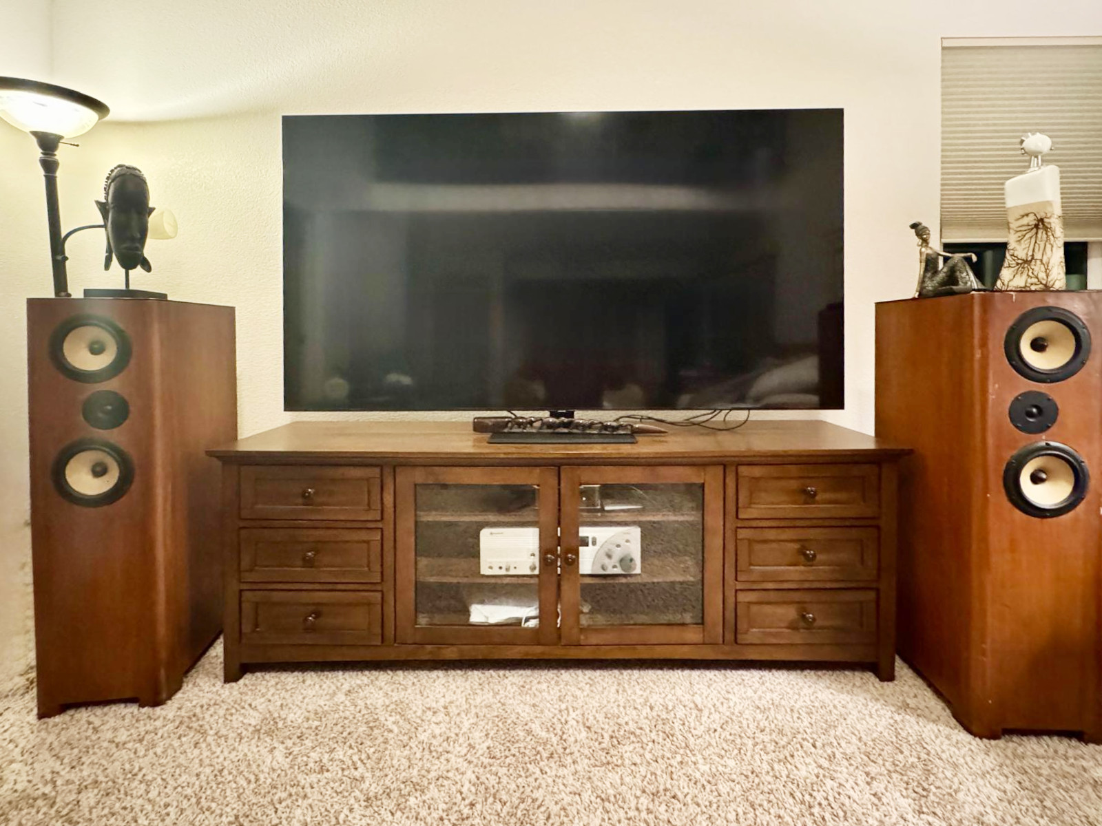
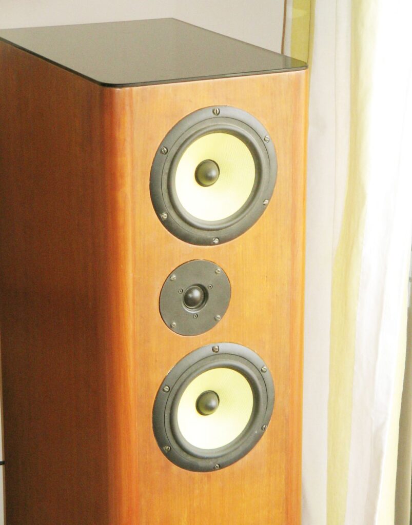
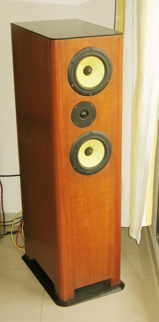
The midbass driver remains the same. The enclosure is still a floor-stander, and at first glance, someone who has seen the original Asawari will probably mistake the Mk II for the original, specially from the front. From the side, the reduced depth is unmistakable.
The tweeter has been replaced primarily to allow me to try a lower crossover point. I wished to see whether the sound of the midbass driver changes if I restrict its reach into the higher frequencies. The North D25 is (was) a very affordable tweeter. IIRC, it cost me less than $20 each, and John “Zaph” Krutke has reviewed it and found it to be quite a decent performer. At that price, I doubt there is (was) any tweeter which performed so well and also allowed such a low Fc. At $20, its price was comparable to the TG25 from Peerless India.
One sad side-effect of this is that no one else will be able to make the Asawari Mk II. North Creek has stopped selling drivers though they still make them. Peerless India ran out of their stock of the Kevlar cone midbass before even the Mark II was completed. There is a black Kevlar cone driver with a very similar basket and surround, but with different T/S parameters. Therefore, the Mark II will not be copied.
If I had to replace the D25 with another driver which delivered excellent performance for a low price, probably the next driver I would look at would be the Seas TBFC/G and TDFC models. They cost less than $40 each, I believe.
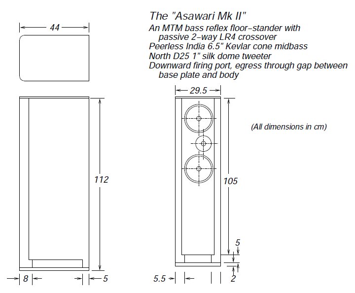
The enclosure
The enclosure is very similar to that of the Mark 1, as expected. As described in the introduction, it’s not as deep as the Mark 1, and has a smarter looking base, a lighter looking glass top. Otherwise, one could mistake the Mark 1 and 2 for each other.
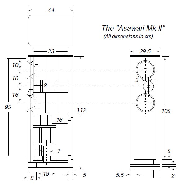
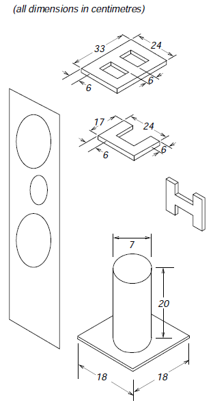
As is evident from the internals drawing, there is no crossover chamber. There is a separate chamber for the tweeter. The horizontal braces just in front of the crossover area are C-shaped, as shown in the exploded drawing below.
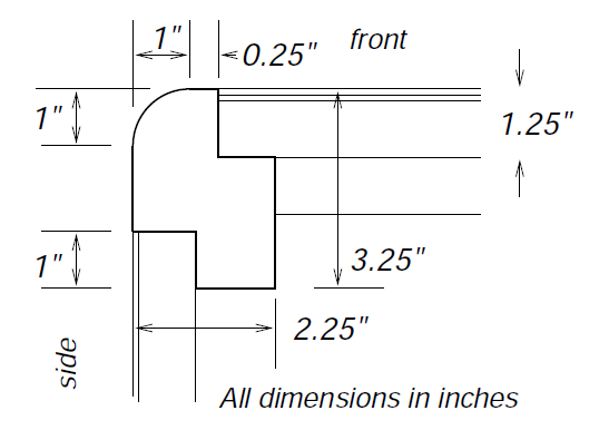
The corner detail is very similar to that of the Mark 1, except that we are using 25mm MDF sheets here, instead of the 20mm plywood used there.
The result is quite delightful, a better-looking monkey coffin than the Mark 1, primarily because of the better surface finish and better real-wood veneer (found some excellent American cherry veneer which matches the colour and grain of the same type of timber used for the corner pillars). I used PU (poly-urethane) polish here. The carpenter applied about five coats of sealant each rubbed down with emery paper, and the final PU coat was sprayed on.
The yellow colour of Kevlar cones makes any wood-finished speaker look good, so it must sound superb. рџ™‚
The recessing for the drivers turned out quite well. There’s 6mm of recess for the tweeter, and one veneer-sheet-deep recess (about 3mm) for the midbass units. The midbass units are supposed to be surface mounted, and have a very thin gasket below their flange for air sealing. But the Mark 1 had taught me that they seem to rise too much above the surface of the baffle that way — more than a millimetre. Therefore, this time I recessed their cutouts by about 3mm, and added a gasket made of thick packing sheet to fill the recess. The driver, with mounting screws correctly tightened, goes into the recess just enough for the edges of its flange to align perfectly with the baffle surface.
The crossover
I had decided to try a lower crossover point in the Mark 2. The SPL and impedance measurements went off without too much problem, once I re-learned Speaker Workshop and recollected how to work with (i) an outboard USB sound card, (ii) an impedance jig, and (iii) set volume control levels.
The woofer and tweeter SPL curves turned out to be as follows:
The phase shows less jagged edges than one usually sees in a raw reading because I cleaned it up by adjusting delay. I had to use 19.4msec of delay adjustment to get the phase plots to clean up.
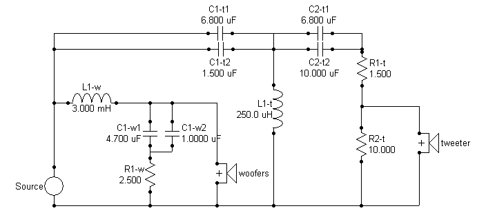
Then I applied a conventional crossover on the woofer and tweeter, along the lines of what I had seen Roman Bednarek do for the Mark 1. This is what I got.
If the fc is the frequency of the sharp point of the notch, then as per the modelled response, I’m getting an fc of 2060Hz or so. Not exactly as low as my original dreams, but low enough for me to meet my design objectives.
The reverse-phase null is quite deep — deeper than what I’ve seen earlier. However, the crossover components all appear to affect the phase coherence of woofer and tweeter. Even small tweaks of value seem to make the reverse null shallower by 8-10dB. This means that normal errors of tolerance in value will make the phase coherence much worse than the modelled ideal case. Also, most of the values are non-standard, needing passives in parallel or series sets.
There is a 3-4dB peak in the tweeter response in the highest octave. The official literature of the tweeter says that this is a designed-in feature. The idea is that this peak in the on-axis response will reduce to a flattish curve in a typical listening setup where the listener listens at about 15 deg off-axis.
When you look at the values in the crossover circuit, you know you’ll never get those values. Capacitors are the most painful to tune, inductors — which are made to order — are the easiest. Therefore, I plugged some real-world capacitor values into the simulation circuit in Speaker Workshop, and tried to see what I get. I was glad that I finally managed to get an almost identical set of SPL curves with the new values, after tweaking resistors and capacitors. In simulation, I’m getting the 30dB notch just as before. I was happy.
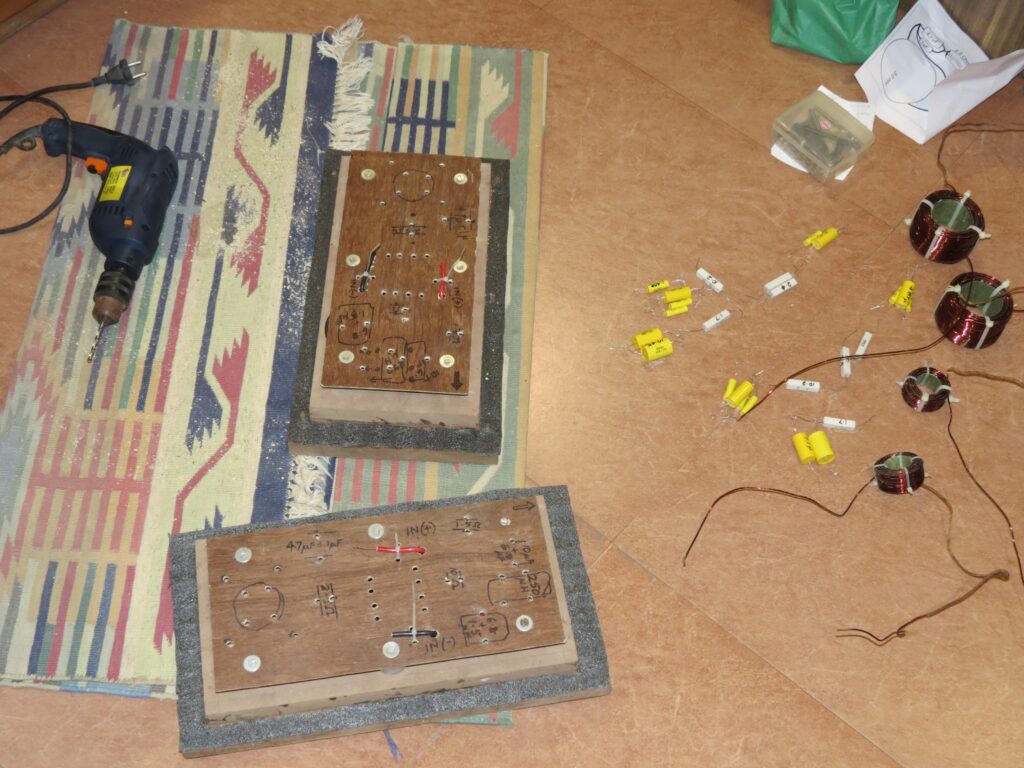
Bought the crossover parts. The resistors are ordinary white-coffin 10W power resistors, as with the Asawari Mk I, and the capacitors are metallised polyester (DEC/MER, yellow cylinders), rated at 250V, from Ramesh Electronics in Kiln Lane, off Lamington Road. They cost me a total of less than Rs.400.
The inductors were a pain. The Bangalore based Corrson has gone out of the DIY audio business, and no one that I knew of could make a coil if I gave broad specs (wire gauge, value of inductance). Everyone wanted to know “how many turns, what former diameter, what length”. So I used some online inductance calculators and arrived at a spec — “X turns of 16В SWG copper over a former so many inches long and so many inches in diameter.” I added 10-15% additional turns to ensure that the inductors would be higher in value, not lower. A higher value can always be reduced by unwinding the turns. Then I found a party which was willing to make the coils for me, and they made them well. The bill was a whopping Rs.6000 (about USDВ 120 at current rates) for four inductors.
They wrapped the coils in long strips of cotton cloth and dipped the whole inductor in varnish, I think. The end-result was excellent, solid and tight, if I wanted it ready-made. But I did not — I needed to unwind them to bring the value down to the right figure. So I had to unwind that cloth (took an hour to just remove the cloth from four inductors) and sat down with sound card, impedance jig, Speaker workshop and laptop. I found that the 250В uH coils were all between 340-360В uH, and the 3.0В mH coils were roughly 3.5В mH. So I kept unwinding and measuring, till I reached figures which were +/-1 from the desired value in the second significant digit. In other words, I wanted 3.0В mH, and I got between 3.1 and 2.9В mH. For the 250В uH, I got 240-260В uH. That was near enough for me, and the Speaker Workshop inductance readings are never stable anyway — the readings of the same coil keeps jumping more than this amount even if I don’t touch a single wire between consecutive readings. I finally fastened each coil tight with cable ties.
I used 16В SWG copper for inductors. This is about 14В AWG, for my American friends. This was thick enough for my inductors, considering I was not building any low-pass at 200В Hz in 3-way speakers.
I measured the capacitors and resistors too, to get their values close to 1-2% of what the simulation says. I bought capacitors of slightly lower value where possible, plus a dozen 1uF and 0.1uF capacitors, to fine-tune the values if I can by paralleling.
Made a physical layout diagram of the crossover parts on the board.
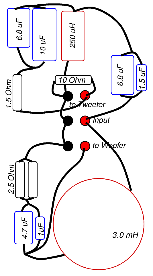
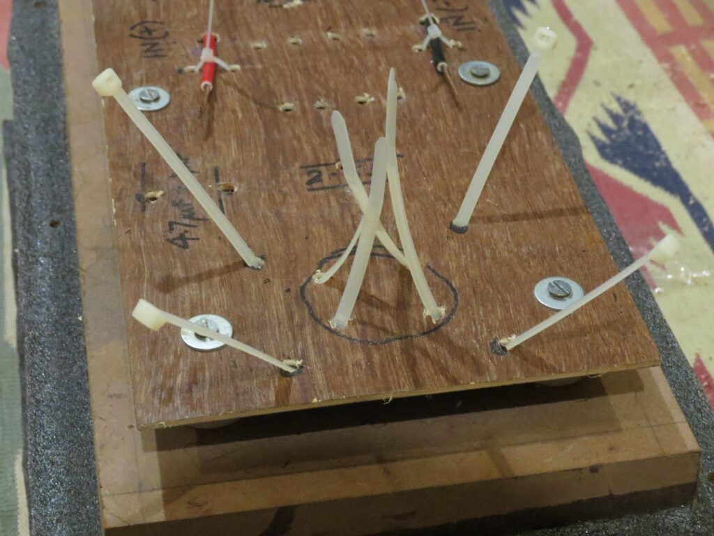
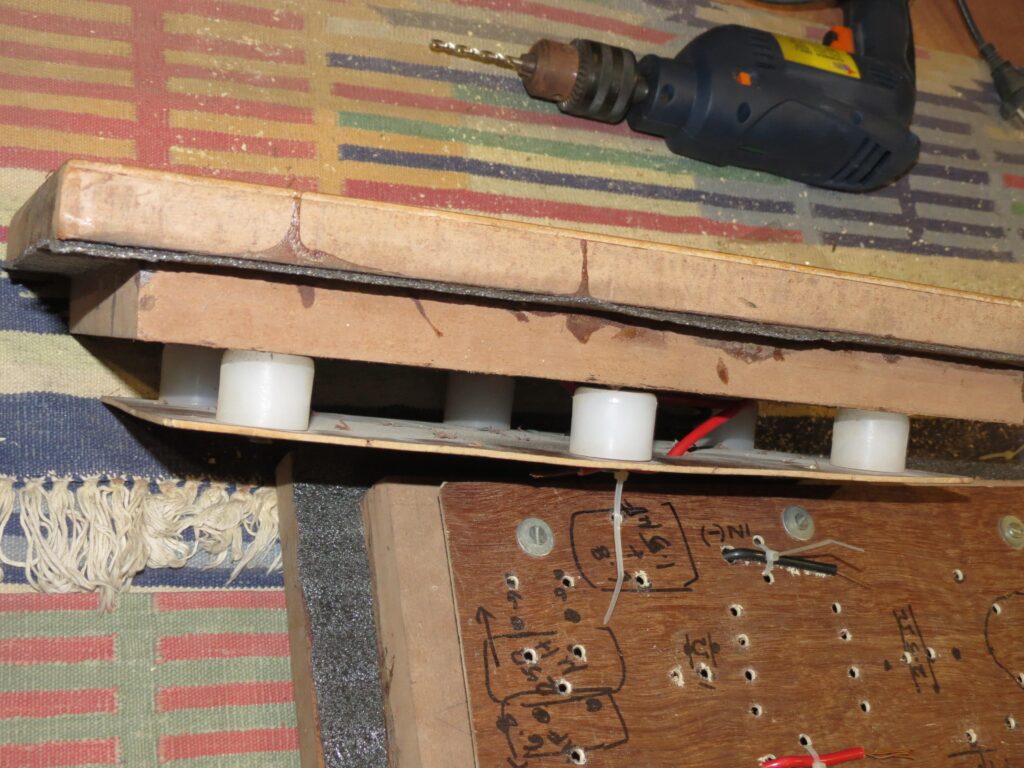
I used my old construction approach of a 3mm-thick plywood sheet as the crossover board. It is mounted just inside the speaker terminals, on 1″-tall nylon spacers of the kind used below cupboards and tables to raise the wooden legs from the floor. I will drill holes in the plywood sheet and mount the parts using cable ties. Then I will solder the parts using point-to-point soldering. I have a lot of 16 SWG enamelled copper wire lying around, having removed a dozen metres of it from the coils while trimming their value. Those will be my point-to-point connecting wires this time.
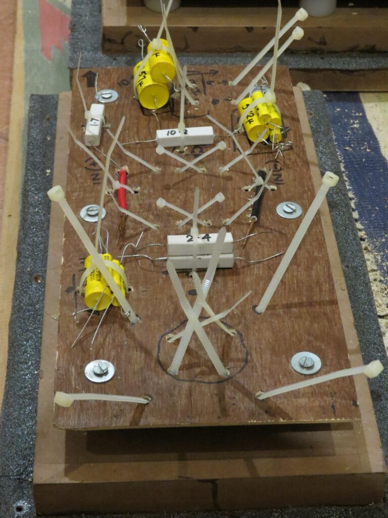
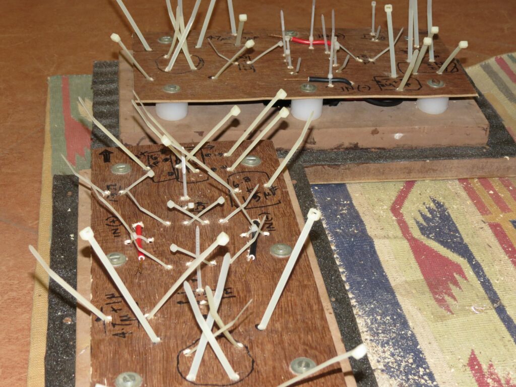
Just in case there are some DIY builders less experienced than me, I thought I’ll put up some photos of how I assemble the physical crossovers. I tie down the components to the sheet of ply using cable ties and then connect them electrically using point-to-point wiring. No printed circuit boards.
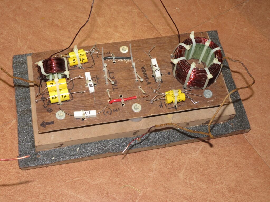
Next step: solder the components, fix the boards back on the enclosure, connect the driver cables to the crossover, and see whether it sounds like a real speaker. This bit was finally completed in August 2013.
Performance
My first impulse is to describe what this system sounds like compared to (my memories of) the Asawari Mk I.
- The bassВ was amazing. I was surprised at the bass extension. I suspect that this was in part because of the smaller enclosure. The Mark I had an underdamped enclosure; this one is only barely underdamped. The bass impact too is better than that of the Mark I, though this was is no disco-party shaker. Things like double-bass in jazz vocal pieces just energised the room with their depth and richness.
- The highs:В The sharp and brittle highs of the Mark I were not there here. I have done no tweeter level tweaking. Listening to the Mark II on-axis may sometimes give the impression that the high treble was a bit too strong. Listening 15-20 degrees off-axis cures this, and I would recommend listening a bit off-axis to all speakers in domestic settings anyway. However, even on-axis, when the high treble is quite strong in some songs, it does not sound brittle like the Mark I, and does not generate listener fatigue.
- Tonal balance:В seems quite even. I played a lot of different genres, from Hindustani classical recorded without almost any processing, to Western music and movie soundtracks. The speakers seem to play back each type of music “in its type”. What is expected to sound soft and warm (Ganpati Bhat, Harry Bellafonte) seemed to sound soft and warm. What is expected to sound hard-edged (theme songs from Bond 007 films) seemed to sound the way you would expect them. Shirley Bassey, recorded in the fifties, sounded a mix of very powerful highs and softer passages.
- Voices:В are breathtaking. I tried Harry Bellafonte to Shirley Bassey, with Mark Knopfler, Chhannulal Mishra and Patricia Barber in between. All of them sounded — well, themselves. Very satisfying.
- Transients:В seem to be very good. Guitar (“Friday night in San Francisco”, John McLaughlin, Paco de Lucia, and Al Di Meola) sounded good. Rock guitar (Mark Knopfler) sounded good. Sharp and clean but without listening fatigue.
- Soundstage:В I was a bit in two minds about this. The soundstage seemed to be more confused than the super-etched soundstage I had heard with the Mark I. Well recorded pieces (e.g.В Chesky audiophile recordings) seemed to have excellent soundstage, but others were a mixed bag.В Update:В More listening indicated that albums which have good soundstage played back with good soundstage. Less than 50% albums seemed to do this. It’s possible that this is a feature of the recording than the speakers, considering that I listen to all sorts of albums from all sorts of genres and recording styles.В Update:В Speaker placement and the “correct” SPL were needed to get a good soundstage. If the volume was too high, the soundstage muddies, no doubt due to room reflections. And if the speakers were less than about four feet from the rear wall, then too the soundstage seemed to get somewhat flattened out.
-
Other traits:
- This system threw up recording quality and environment details amazingly well. You could hear different degree of hall reverberation in different live concert albums. Most hard rock live albums seemed to have mediocre recording cleanness. Chesky albums sounded extremely good.
- The sound seemed very detailed, without any artificial brightness or listening fatigue.
- When playing a symphony album, the loud passages seemed to have a wonderful tonal balance, no harshness (even Deutsche Gramophon’s von Karajan’s Beethoven symphonies collection). And they sounded, for want of a better word, “unforced”, as if showing no sign of strain to handle the crescendos. Those pieces really came alive, instead of merely sounding “loud” and “grand” in a meaningless sort of way, which I used to get from worse systems.
My thoughts about the design decisions
The Mark II is clearly an improvement on the Mark I, in my humble opinion. Three decisions have had an impact on the performance relative to the Mark I, in my opinion:
- selecting a lower crossover frequency: may have cleaned up the midrange and upper mids somewhat
- switching to a smoother silk dome from a harsher aluminium dome tweeter
- The smaller box volume has tightened bass — it is not as underdamped as the Mark I. The 3mH woofer inductor (compared to the 1.5mH coil in the Mark I) has probably added a touch more weight to the bottom of the frequency range — a bit like a touch too much BSC. I left it as it was for now.
There must have been other factors which I could identify, but the Mark II was clearly a different animal from the Mark I.
Drawing the project to a close
My friend who took the Mark II is a Dylan devotee, and also likes most examples of classic rock. He has not started exploring classical music, and seems to hear relatively little of jazz,В etc.
In 2013, I felt I would have to listen to the speakers for a few months to really make up my mind about them — this is true of any speakers. However, I had a feeling I would not be permitted that much time. They found a good home. They are now in Colorado with my friend, who listens to music on them every week. He’s had them for more than a decade and doesn’t seem keen to upgrade. He drives them through an Outlaw Audio integrated amplifier.
Performance tuning
After listening for a couple of weeks, before I shipped them to my friend, I began to feel there was listening fatigue.
There was the sharpness in the extreme highs. This was not audible in “normal” music, e.g. the cold hard lead guitar of rock bands. It was only audible in the case of Shirley Bassey’s voice, one or two other sharp female vocalists, and in some violins. The general case of violins, in Western classical pieces, seemed quite acceptable. In fact, this sharpness was not much of a problem for general listening.
The real problem was lower down, somewhere, and I had no idea what it was due to. It was a kind of edge to male voices, not female. At first I liked it, because it added an edge of heightened detail to the voice, made words a bit more intelligible (even for Mark Knopfler’s mumblings), and made them sound a bit lighter and brighter. This lightness was more audible in Robbie William’s voice, which is not very deep to begin with.
In addition to the male voices, I felt that there was a kind of hard, cold, edge to guitar strums. I am not referring to the sharp transient when the string is plucked, but the sonorous sound when the string vibrates freely later. (Is it better if I say “I’m not talking about the attack, but about the sustain and decay”?) That sound in a good guitar is really beautiful — it is warm and pleasant. Here, there was a slight artificial “fatness” or “fullness” to the sound, and the warmth was less. It is really frustrating describing an auditory experience in words, but that’s our fate, we of the Internet-savvy DIY audio crowd.
Beyond a certain point, I noticed that I was not being emotionally drawn into the music. Long listening sessions were giving me clean sound, good soundstage, etc., but the effortless emotional connection was not happening. I would listen to an entire album and get up and go. This was not good.
Therefore, I pulled out the SPL graph of the speaker and stared at it. When I am clueless, I stare quite well.
Midbass tweaking
The first thing I noticed is that there was a midbass hump in the 2K-3K range which may be adding the hard, cold edge to the voices. So I fiddled with the crossover model in Speaker Workshop. (Fiddling with inductors is harder to do, and adding more inductance is the hardest because I would have to get a new coil made, therefore I left it as the last option.) I figured that if I put a capacitor in parallel with the driver, to shunt some high frequencies away from the driver, I may be able to get the dip I was looking for.
Soon, I had arrived at a new cap, in parallel to the existing ones, which would shunt some of the upper frequencies for the midbass units, lowering the SPL in that region. The change to the crossover looked like this:
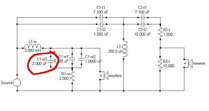
In effect, I was increasing the value ofВ C1-wВ by adding a cap in parallel with the existing two. I had createdВ C1-wВ by paralleling two physical capacitors to arrive at the value I needed; I was now adding a third. I experimented with 2uF and 4uF for C1-w3, to see what the curves would look like. The black line in the plot below is for the original crossover, and the red and blue are cutting the upper midrange level as I increased the capacitance of C1-w3:
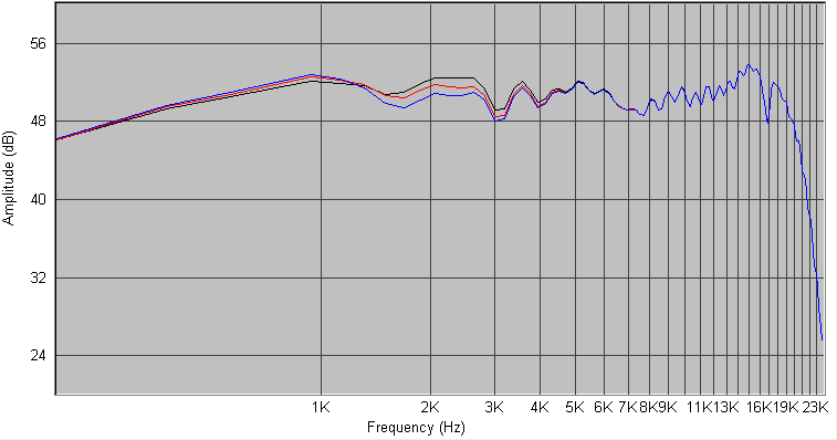
Taking a closer look by expanding the Y-axis in the region of interest, I get:
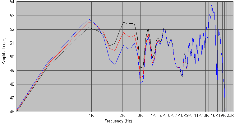
I could see that every 2uF of additional capacitance was bringing down the level in the 2KHz-3KHz range by about 1dB. Cutting the level by a couple of dB, followed by listening tests, would be needed.
Tweeter tuning
Then I focused on the tweeter. This one needed a bit more experimentation with the modeled crossover, to figure out how to achieve what I wanted. I wanted to cut the hump of 9KHz and above, flatten it. I figured that this would take away the edge in the extreme highs. In effect, I wanted a low-pass filter on the tweeter with a turnover frequency somewhere above 8KHz.
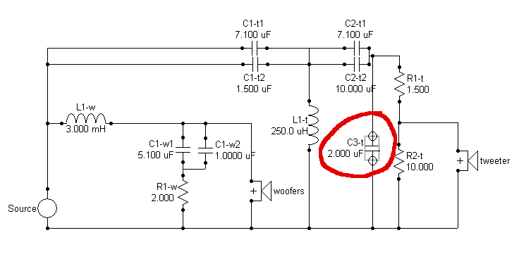
After some experimentation, I realised that a shunt capacitor across R1-t, R2-t and the tweeter is sort-of doing the job. It is able to cut the extreme highs, but it is also cutting everything from about 4KHz and above. I would have loved it if I did not have to cut the mid-treble band, but a single cap cannot achieve this, it seems. However, for what it’s worth, this is what the additional capacitor looks like in the circuit:
To see what values would work, I tried 1uF and 2uF. The black line is for the original crossover, and the two coloured lines are cutting the treble as I increase the capacitance.
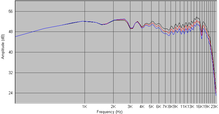
And zooming in on the region of interest, this is what it looks like:
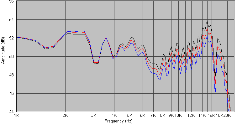
It is cutting the extreme high treble (9KHz and above) all right, but it is cutting the rest of the treble too, to a lesser extent. If I put in 2uF, I am able to cut the 14K-16K region by about 2dB, which would definitely clip the edge off the extreme highs. But I would also cut the 5K-8KHz range by 1-1.5dB, which I would have liked to leave untouched, ideally.
It was also increasing the 2KHz to 3KHz zone a fraction of a dB per uF. Adding 2uF tweeter shunt was increasing the zone of 2K-3KHz by about 0.5-0.75dB This is the zone I was trying to cut down using the midbass capacitance tweak.
I am sure a better way of handling the tweeter’s top-end hump would be by adding a second-order low-pass stage, with an L and C, but I did not go that far.
What I did finally
I added C1-w3 to the speakers, value 3.3uF. It changed the tonal character of male voices beautifully, and removed the hard edge from guitar strums. The listening fatigue disappeared. Whether I should have used 2.2uF instead of 3.3uF is an open question.
I have not done anything to the tweeter crossover. I figured that the edge which is bothering me is audible only in some tracks. Even music which is well known as being somewhat bright (Dire Straits, Billy Joel) does not trigger this edge. I chose to leave it as it was.
There ain’t no such thing as a free lunch. By cutting down the upper mids a bit, I got rid of the fatigue. But as a result, the voices receded into the background a bit. Earlier, their edge would make them appear more forward, making for very powerful vocals. Now, the vocals merged into the rest of the soundscape a bit. Wish there was a way to keep the voices powerful and forward without the listening fatigue. Ah, well.
What I learned
What I was really kicked about is the learning I got. Initially, this cold, hard edge in the upper midrange had gotten me quite disheartened. I was wondering whether this was one of those unmeasurable, intangible, unspeakable, unfathomable things which separate the truly great speakers from the also-rans. I was wondering whether this was a problem of the speaker drivers. Now I know that this thing is measurable, visible, and has a cause-effect mapping. The Asawari Mark II is not a top-class speaker, but there is nothing intangible and unfathomable about its performance.
I am glad that the problem was in the SPL curve, in the crossover, not in the enclosure. (At one point I was wondering whether the problem was due to some unidentified resonances in the enclosure, due to any flaw in the enclosure construction.) Now I feel more confident that I can deliver enclosures of large floorstanders without worrying that they will screw up the sound.
I am convinced that the problems in a real-world crossover are with the peaks. All experienced speaker designers keep saying this, but I had to experience it for myself. The troughs in the SPL curve are not so much of a problem; the peaks needed to be tamed.
I was impressed at the final quality of sound I was getting from these mid-level Peerless India drivers. They are capable of delivering very good performance in the hands of an experienced speaker designer.
Before the tweaking, the sound was “hi-fi”. I find it very hard to define what this means. It sounded “high end”, with a clarity and edge to various voices and instruments which made them stand out so impressively. After the tweak, the speaker sound was less impressive. It is more natural, but it lost its “high end” edge. I now realise that dramatically impressive sound is unnatural, and this is a fine dividing line.
I am convinced that a good tweeter makes a difference. The secret is not just in its SPL curve. My tweeter has a sharply rising SPL curve towards its top end and yet it caused less harshness than the aluminium dome tweeter I had used for the Asawari Mark I, and that tweeter’s SPL did not have such a peak. I will choose good tweeters henceforth, with care, and these North Creek D25 are my base line. Once I run out of these, I will go for the Seas TDFC fabric dome. I will be hesitant to touch metal domes. (Today, in 2026, I look at SB Acoustics tweeters as the baseline instead of the Seas.)
And I now have new respect for the correlation between the SPL curve of a speaker and its subjective performance. I will be more careful to get the SPL curve “right” in future designs. And I will pay a premium for drivers with a measurably smoother SPL curve.
-x-x-x-x-x-