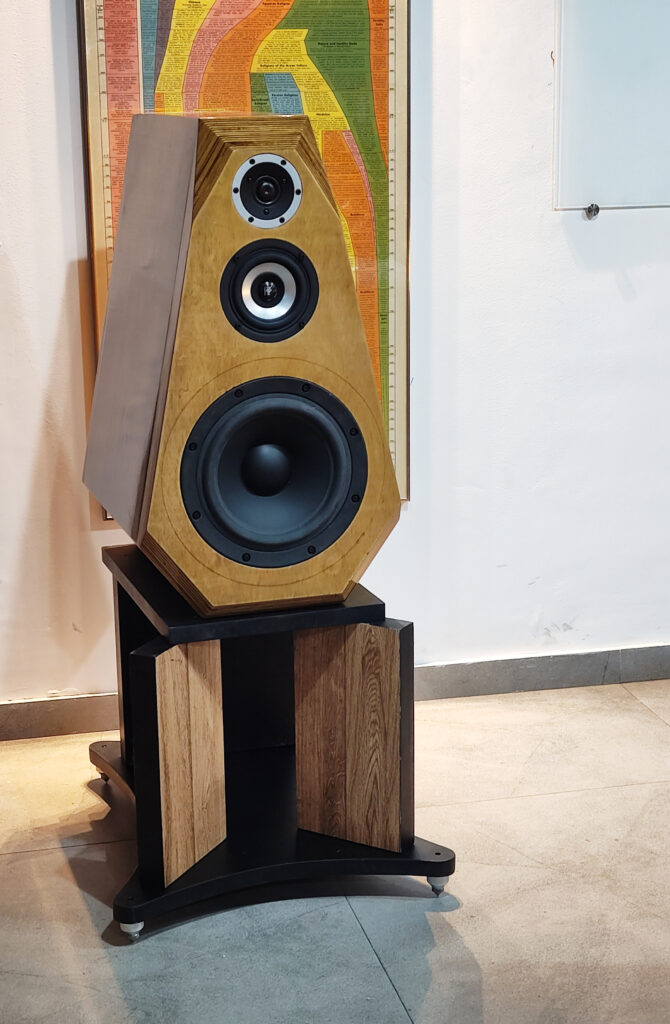
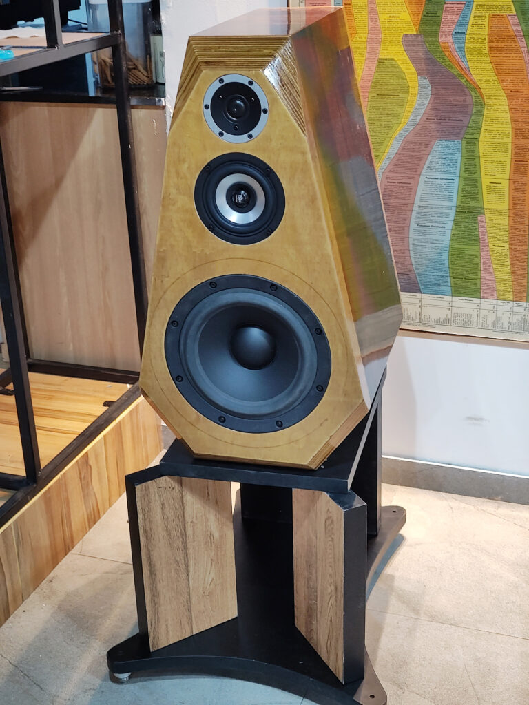
The Shankara is the first of a family of 3-way designs all of which look similar. (The Adana is the first of a similar family of 3-ways which look very different from the Charukeshi line.)
All the Charukeshi designs
- Are 3-way designs, large standmounts, with a TMW configuration
- Some are purely passive xo, others are hybrid active-passive, like the Shankara
- The ones with a passive xo are ported, the active xo designs are sealed
Design notes
After The Darbari, I decided to try new designs with the same basic principles but with simpler build and higher quality of drivers. (After all, the planning for the Darbari and that for the Shankara had a 12-year gap, in between which I had had the pleasure of living with the Darbari for a few years.)
- Basically, stick to 3-way and an active crossover for at least the low frequency crossover. I did not feel the need for an active crossover and an extra amp channel for the high frequency one.
- Make the speaker smaller by choosing a more sensible woofer which could deliver in a smaller box volume.
- Stick to a 10″ woofer; that size had proved adequate with the Darbari. But pick one with greater power headroom, to allow better active equalisation if needed.
- Use better, more expensive drivers, to see what they bring to the table. Specially, get a midrange which can handle a wide range of frequencies and deliver outstanding results.
- Do a one-box solution.
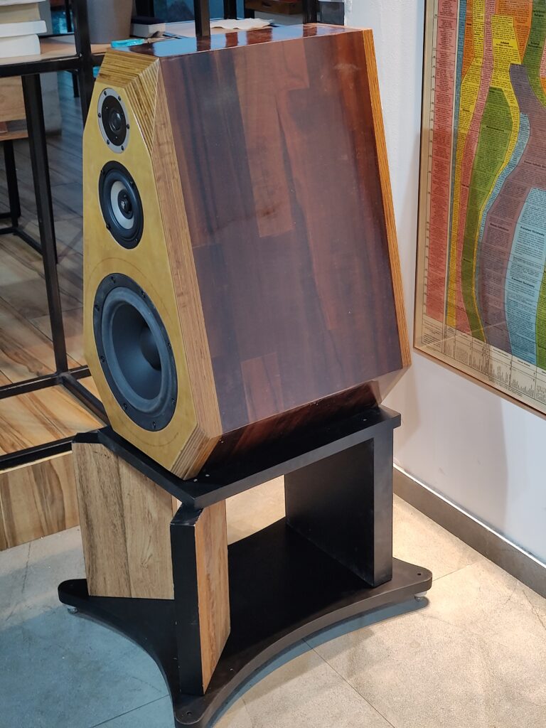
- Continue to strive to make an appearance which breaks the rectangular-box impression. (Even the Darbari didn’t break this illusion adequately; its woofer enclosure was a large rectangular box.)
Luckily, I had a larger budget to build with than during the Darbari period, so I could choose expensive drivers.
Drivers
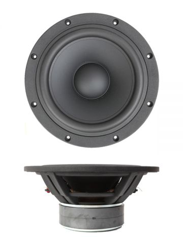
The woofer chosen was the SB Acoustics SB29NRX75. It gave me a sensible size for the enclosure, adequate power handling, very good cast-frame build quality, reputed manufacturer credentials (which means I could trust the T/S parameters published), and I wasn’t thinking much beyond this. But I had considered other attractive options too.
The Dayton RSS315HF is attractive, but a bit larger than I wanted. There was one Scan-speak Revelator 26W, one Seas Excel W26FX, a few Seas Prestige models. Nothing in the Dayton RS range seemed to be an improvement over the Darbari’s RS270.
The midrange was a special star performer, a descendant of another boutique superstar I had worked with 20 years prior. I chose the Jordan Eikona 2. I had experienced the magic (and the limitations) of the JX92S, and had always wanted to try the Jordan with assistance at the top and bottom. The Shankara would be a good place to try it out. Unlike a normal midrange, the Eikona would be able to go lower, so a crossover at 150Hz was considered. The top end of any full-range (or “wide range”) driver needs assistance from a good tweeter, IMHO, so that would be provided here, perhaps at a conventional frequency like 2.5KHz.
In this design, I was going with the midrange being the star of the show, with the other two drivers just being so good that they should not prove to be the weakness of the overall system.
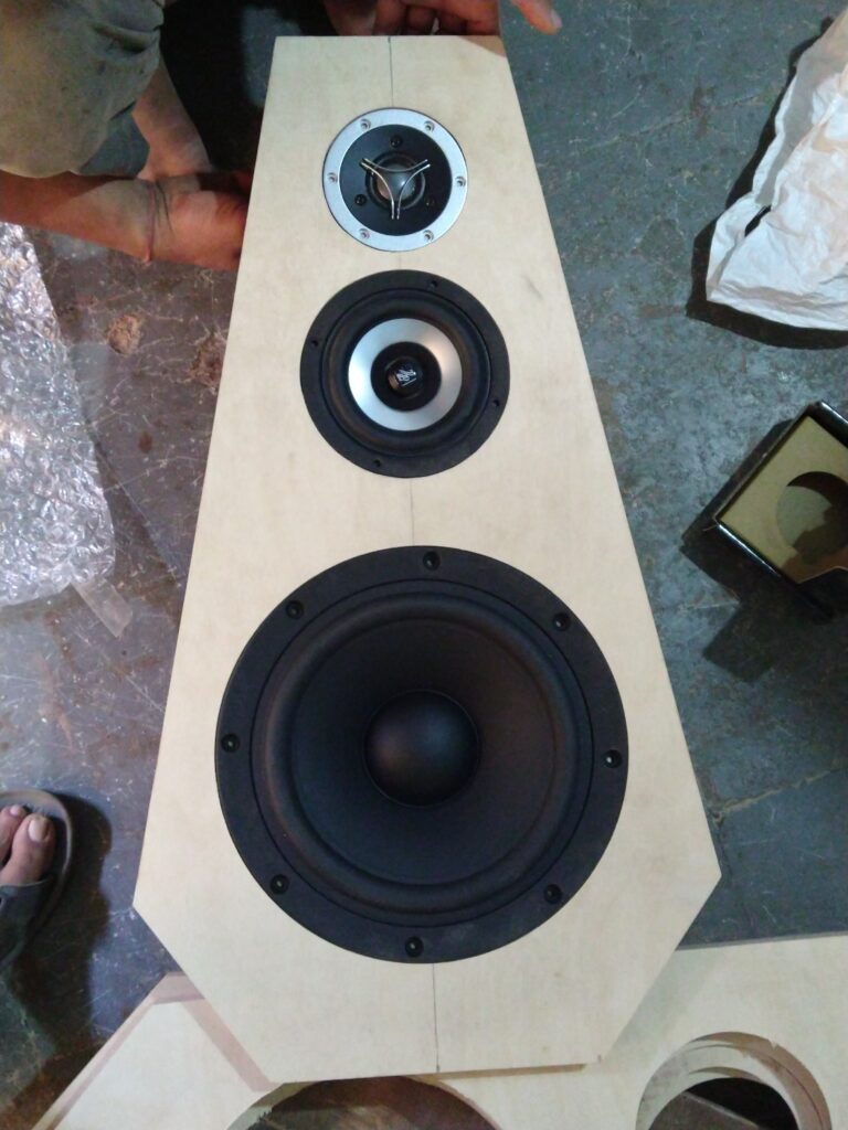
The tweeter was just something I picked based on glamour and price, not because I had extensive use-case details from others. I picked the beryllium tweeter from the Satori range, just to provide a detailed, very low distortion top end, and get out of the way of the Jordan. This was, therefore, the TW29BN.
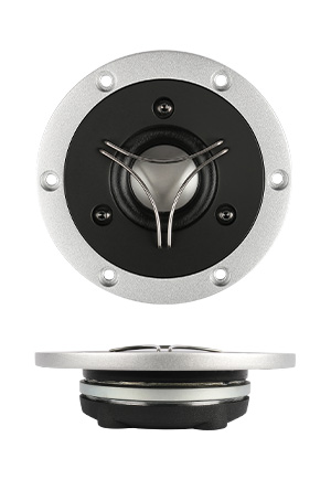
The dual-colour front-plate of this variant was so cool, I thought. This went well with the dual-colour looks of the Eikona. “If it looks great, it’ll sound great too” — old jungle saying.
(Note that the photo above shows the TW29R ring radiator, not the beryllium dome TW29BN; that was just placed there for trials.)
The enclosure
The woofer needed a sealed box, so Unibox gave me something like this:
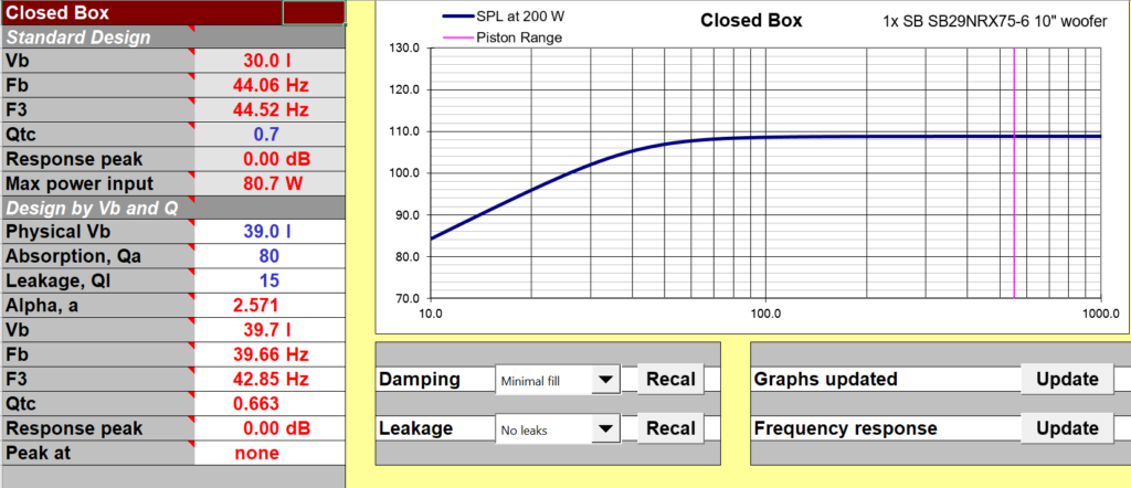
I chose a 39-litre sealed box, getting a Qtc of about 0.65. I believe that the real-life in-room response from such a box would be indicated by the F10 frequency, which in this case is about 25-27Hz. I do not need anything lower than 30Hz in-room, so this was excellent. I may not need any Linkwitz Transform at all — I’m building for jazz double bass and symphony orchestra timpani, not for a disco or EDM. (I’m probably not even building for the lowest notes of a pipe organ.) The ability to go this low without equalisation in a sealed box partly comes from the driver’s very low Fs: 21Hz. This is indeed a gem of a woofer. Unibox looks at the driver parameters and recommends a sealed box for it — see “Suggested box type: Closed” below.
We had the box volume for the woofer, and we had an overall shape to aim for, so I arrived at a box design which looked like this. All dimensions are in centimetres.
The diagram below is the overall enclosure drawing. The red circles indicate the outer flanges of the drivers; they will be visible on the baffle. The continuous-line black circles are the cutouts, as seen from the front. The dashed-black circles show the inner edges of the bevelled cuts for the drivers.
The diagram shows the outer sheet of the two-sheet front baffle. Red circles showing outer mounting flanges of drivers, dotted-line circles show the inner edge of the bevelled circle, not visible from the outside, and full-line circles show the edge of the cut as visible from the front. As can be seen, the outer sheet of the baffle shows no bevelling for the woofer and tweeter, but it’s there for the midrange.
The diagram below shows the inner sheet of the front baffle. There is total bevelling here for the woofer and midrange, thus making the inner edge 5cm larger than the outer (45-degree bevelling in a 25mm sheet means 50mm increase in diameter. The tweeter of course has no back wave and needs no bevelling.

This diagram shows the rear baffle which will be screwed on from the back.

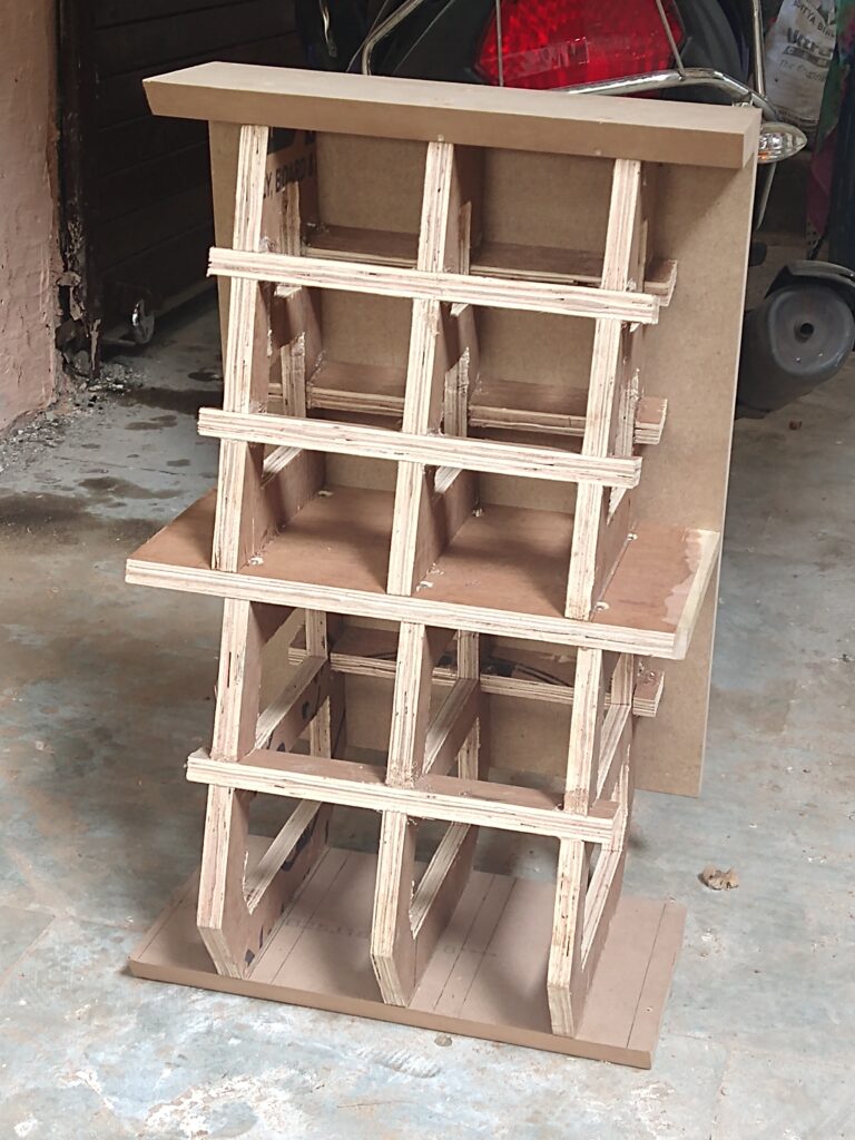
These are the interesting internal bits. They are the interesting braces and frames which hold the walls in place. They are made out of 20mm plywood, not MDF. The outer walls are made of 25mm MDF, the front and rear baffles are made of 25mm Baltic birch plywood.

Things will become clear as the construction photos are studied. The next photo shows the frame being put together. It shows the bottom sheet (25mm MDF), the top sheet (MDF again) and one sidewall sheet (MDF). The internal space is divided horizontally into an upper half and a lower half. The upper half is for the midrange (and also incidentally, the tweeter) and the lower half is for the woofer. The lower half has three vertical frames, and so does the upper half. There are horizontal cross braces holding the vertical frames together and also providing a skeleton to fix the walls.
Note that the woofer needs to extend deeper inside the enclosure and the middle cross-bar of the first frame in the lower chamber will prevent the woofer from being inserted. So, that cross-bar of the first frame will need to be sawed off after the assembly is partially done.
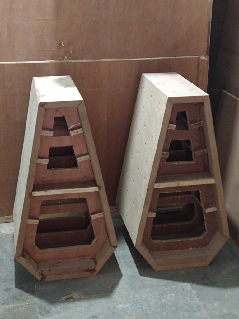
Another view of the skeleton.
Here one can see the full enclosure ready, with top, bottom and sides fitted. I like to have a double-thickness bottom base, so that second sheet of MDF has been fixed. The cross-bar of the first frame of the lower chamber has been sawed off, thus giving space for the woofer to extend inside.
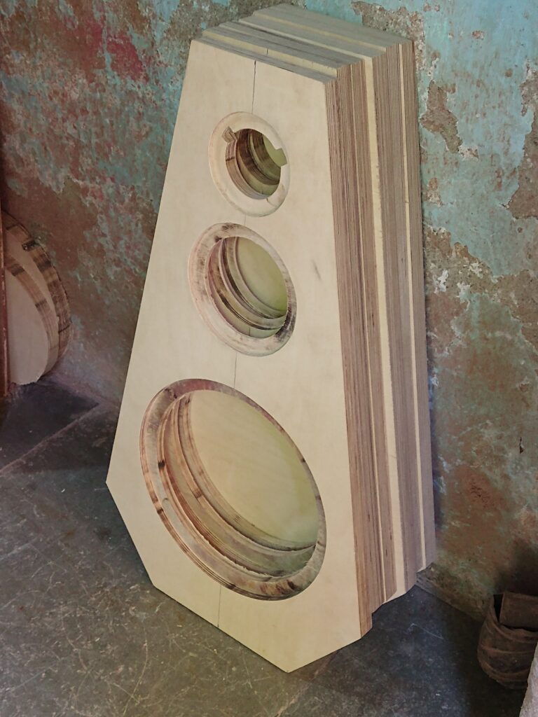
The next image shows the outer front baffle, with recessed cuts for all three drivers. This is a check to see that the recessed cuts are all of the right size.
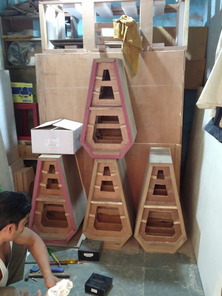
Another photo of the same setup, showing half-built enclosures of the Shankara and the Charukeshi Mark II. Their enclosures are identical, bar the different cutout sizes for the midrange. (The Charukeshi Mark II uses a Satori MR13 midrange.)
The next photo shows the outer and inner baffle sheets of the Shankara ready. The bevelling of the front baffle is not done at this stage. It is done after the sheets are fitted to the body.
The next photo is a fast-forward to post-construction, post-polishing stage, where one of the enclosures is lying on the bottom plate of its crate. Each speaker gets a purpose-built wooden crate for transport.
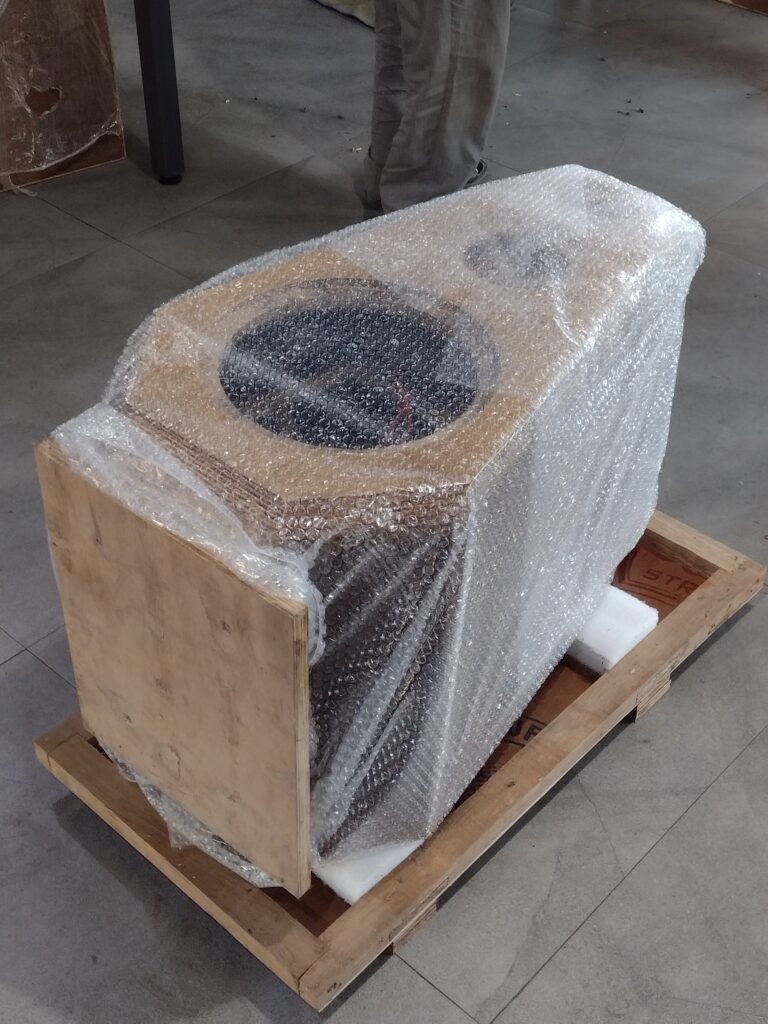
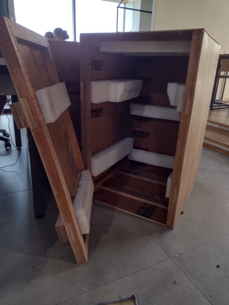
This is what the inside of a crate looks like. Two-inch thick expanded polymer foam sheets are cut to size and shape to hold the speaker “floating” inside the crate.
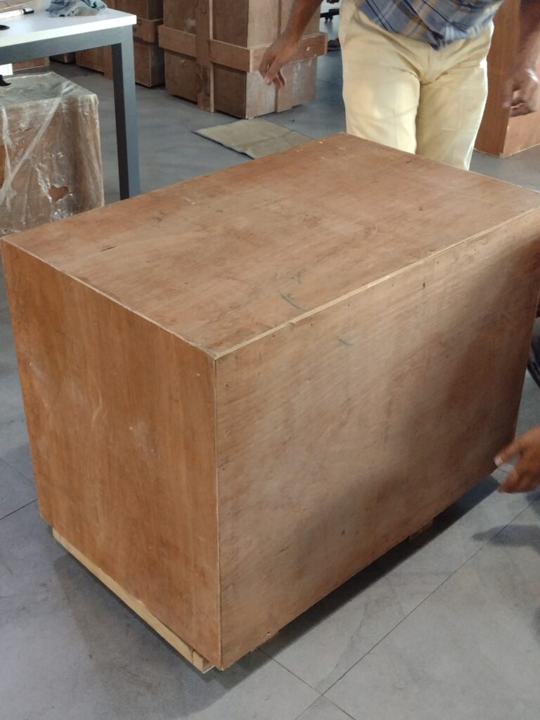
After the top of the crate is lowered onto the speaker, this is how it looks, closed and bolted. There are four or six 4-in long bolts holding the top chamber of the crate to its base. D-nuts inside the crate base lock onto the bolts.
Since the Charukeshi series of designs are not floorstanders, they need good stands. Each variant of the series comes with its purpose-built stand.
Measurements
Lots of measurements, partly to ensure that I don’t have to set up the mic another day and take some missing measurements, and partly because it’s fun. рџ™‚
My usual measurement rig includes a calibrated XLR measurement mic, a Focusrite Scarlett 2i2 set to 96Ksamples/sec, and ARTA.
The tweeter(s)
I had the TW29BN for the Shankara, and the TW29R for the Charukeshi II, so I had fun measuring both.
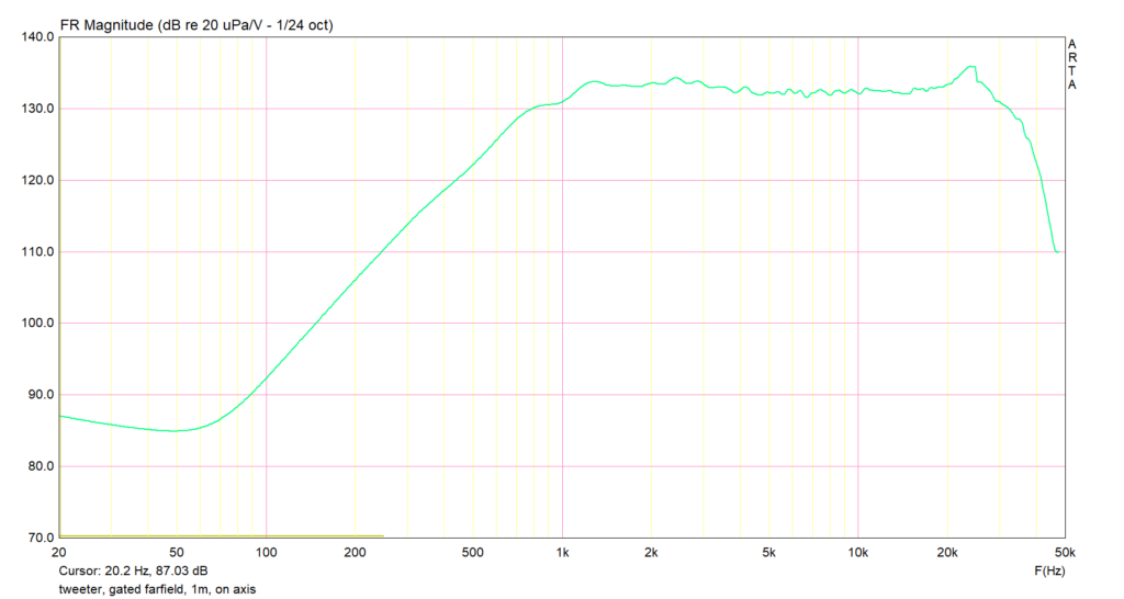
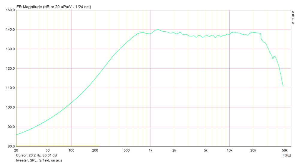
The SPL of the TW29BN, on axis, gated farfield:
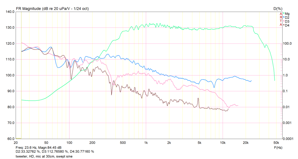
Harmonic distortion of the beryllium tweeter. Ignore the blue line (2nd harmonic) and anything lower than about 1.5KHz, and you can see that distortion is very low.
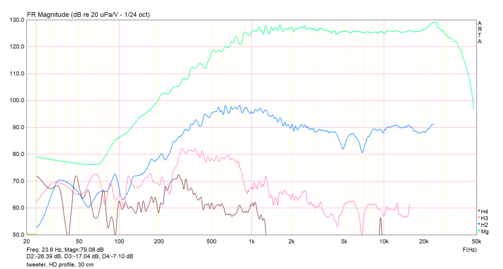
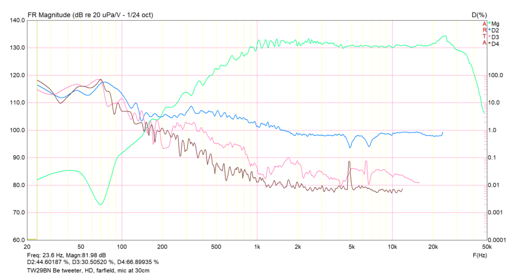
The same data plotted on a percentage scale, in case it helps sometimes:
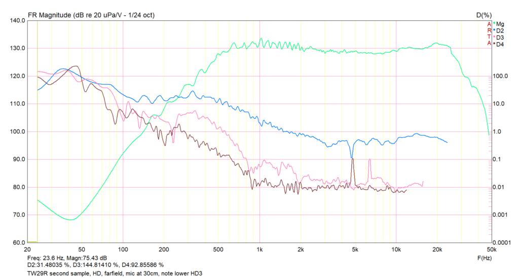
Now for the sibling, the TW29R ring radiator. First, the SPL:
Harmonic distortion of ther TW29R. Clearly a different animal from the beryllium tweeter. Since I had two ring radiators handy, I decided to measure both.
The midrange
I next worked with the Eikona. This needed the most extensive measurements, because the midrange needs to fit into two crossovers at the two ends, and needs the merging of nearfield and farfield measurements.
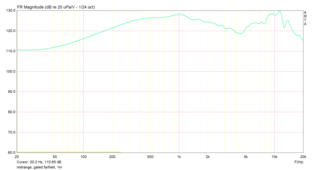
The first reading is of SPL, gated farfield, on axis:
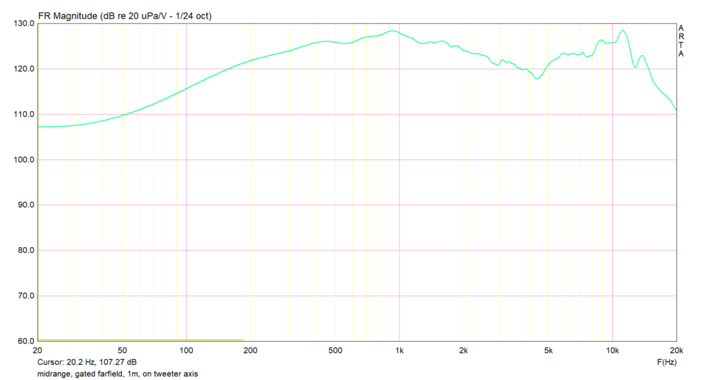
I then wanted to see what this would look like on the tweeter axis, so I did another gated farfield, same 1-metre distance. Hardly any difference.
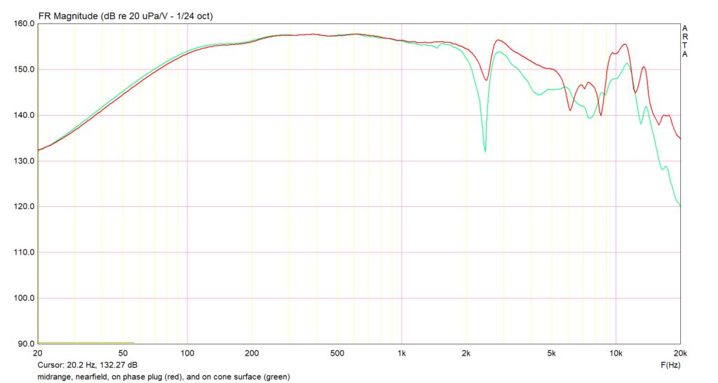
Then I finished the nearfield SPL measurement, keeping the mic first 5mm from the cone surface, then 5mm from the phase plug, just to see what it would look like:
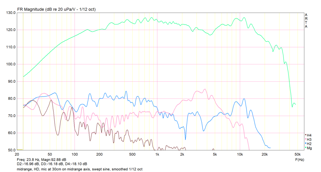
Then I did the various harmonic distortion readings. For low frequency HD measurements, the mic needs to be a few mm from the cone, and for HF HD, the mic was kept 30cm from the cone. (This is my standard practice; I did the same for the tweeter, except that for the tweeter, it’s all 30cm distance, since there is only HF.) The next reading is at 30cm distance, on the midrange axis. All HD data below, say, 500Hz, should be ignored. It’s interesting to see that there is an ugly and wide peak in the third harmonic distortion in the 3K-6K range — exactly the region where the ear is most sensitive. This will give the driver its “personality”, and some will love it, others will dislike it.
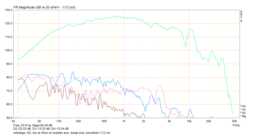
After this is a 30cm reading on the tweeter axis (just because I was feeling like it). It’s interesting to see that both the base SPL curve and the levels of distortion drop in the higher frequencies when we move off axis. As expected.
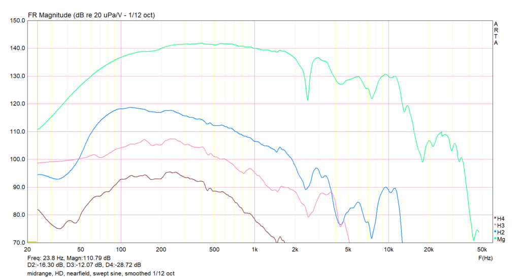
Next was the nearfield HD measurement, to see how the midrange distorts when handling, say, voice frequencies. In this graph, I feel that everything outside the 100Hz-1KHz range should be ignored.
That was the midrange story. It was interesting to get some data, however useful or insightful, on a legendary boutique driver.
The woofer
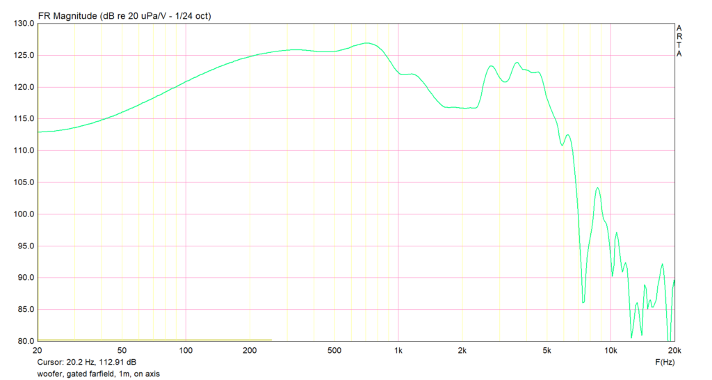
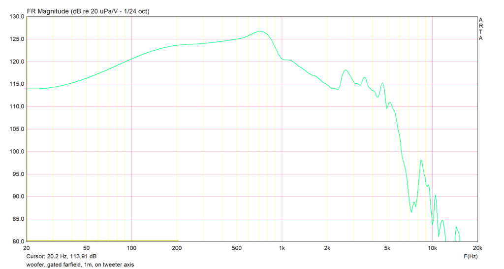
The first reading was the classic on-axis 1-metre gated farfield, which is a useless reading for a big woofer, but needs to be done as a matter of principle.
Then, for fun, is the same reading on the tweeter axis. As expected, the HF drops off. As I said, this is not done for usefulness, more for I-can-do-it spirit.
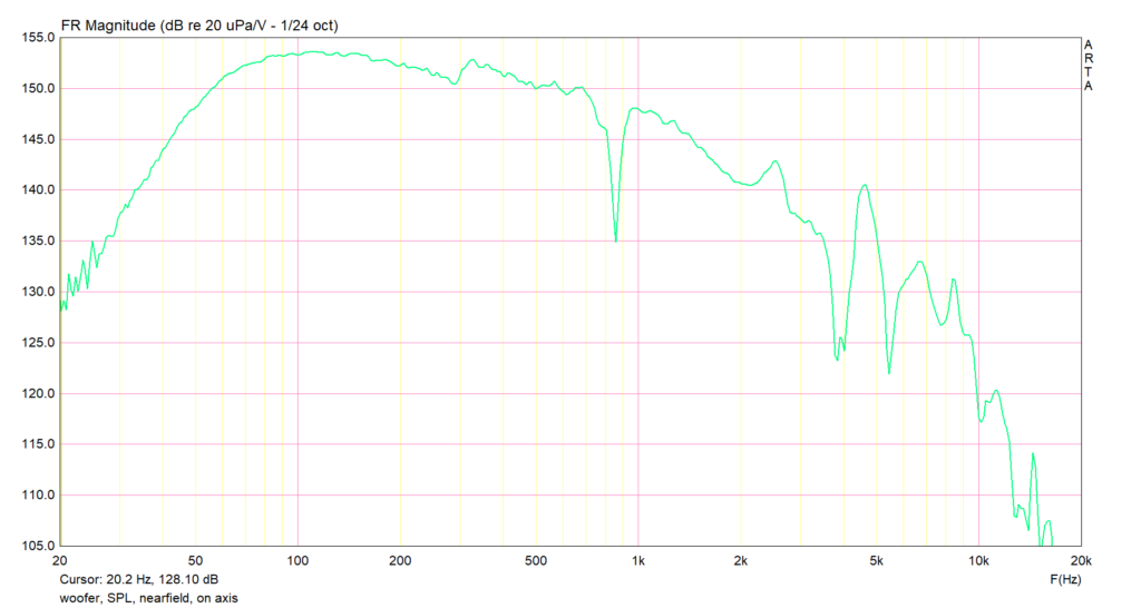
The next is the nearfield SPL. (Note that this is a sealed woofer design. Not that this has any impact on the measurement process.)
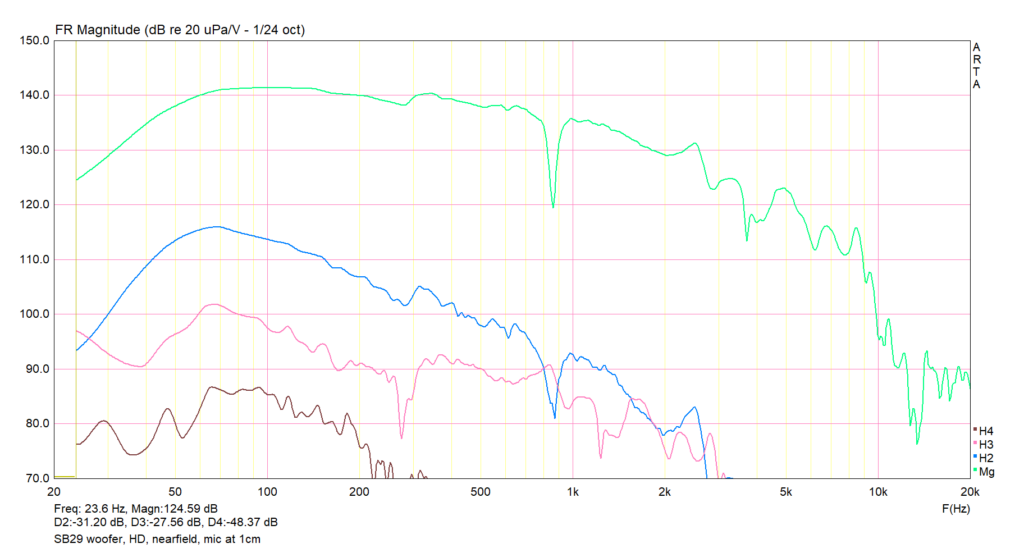
Next is the HD measurement. For a woofer, there is no need for anything other than nearfield. The first reading is with the mic 1cm from the cone.
The next is with the mic 5mm from the cone. I cannot explain the difference.
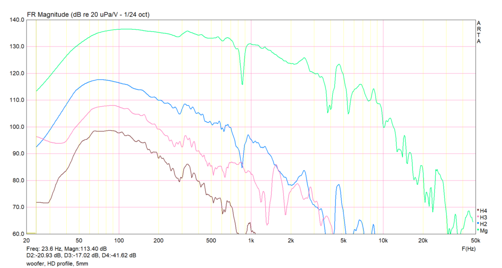
Anyway, we now had enough measurements to design the crossover.
The crossover
This crossover would have two active stages, one feeding the woofer, the other feeding the midrange + tweeter. Downstream of the second amplifier channel, there would be a passive crossover to split the midrange and tweeter.
After a few weeks of fiddling with the active filter stages of VituixCAD, this is what I came up with:
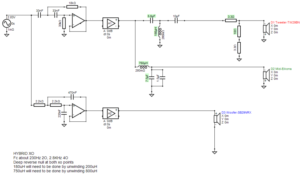
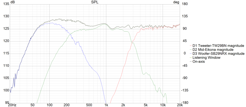
The modelled SPL from this crossover looks like this:
And in case anyone is interested in the impedance of the mid+tweeter branch, this is the impedance:
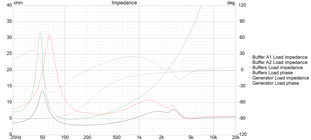
I will experiment with the hump at 1KHz to see if it adds colouration. If yes, it will be easy to use a parametric EQ to notch it out.