The Asawari Mark V was conceived together with the Asawari Mark IV after I crossed the Darbari milestone. That milestone taught me many things, which I could carry over into the Asawari range again, even though the Darbari was fundamentally a different animal — it was a 3-way and had digital active crossovers. All the Asawaris are 2-way MTMs with passive crossovers.
From the Darbari, I learned about higher-order crossovers and the beauty of properly tamed metal cone drivers. I also grew fond of Dayton RS woofers and midbass drivers. Their price-performance ratio is unbeaten, and construction quality is superb. So I wanted to carry those lessons over into the next one or two Asawaris.
The Asawari Mark IV and Mark V were conceived of as twins. They were designed together, and there is not a millimetre of difference between the two enclosures in dimensions or construction, because the midbass drivers are almost identical in T/S parameters, and both use (different) tweeters with 100mm flanges (the common flange size for 1″ domes).
Drivers
The Mark V uses two Dayton RS180-8 aluminium cone midbass drivers in parallel, and Seas 27TDFC fabric dome tweeter. The combination was chosen to deliver very high quality on a reasonable budget. I didn’t want a budget as tight as the first three Asawaris, but I did not want to get into Scan-Speak territory either.
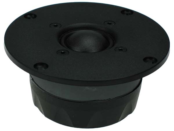
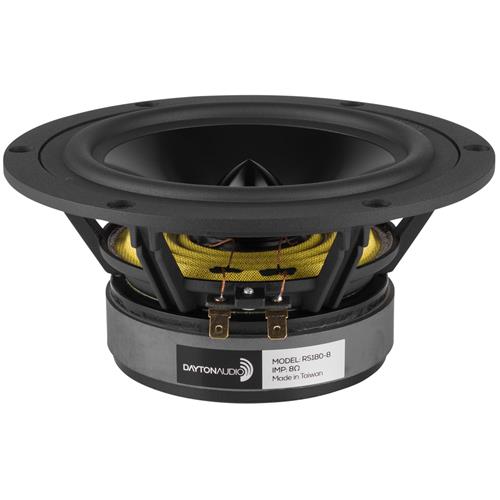
The choice of the midbass drivers was foregone — I embarked on the Asawari Mark IV and V projects because I wanted to use these midbass drivers to build good MTM designs. Why did I choose this tweeter? It’s because it’s the most low distortion, high performance tweeter available at this price. This tweeter is perhaps 12-15 years old, I don’t know, but it’s still almost impossible to beat at its price. Current price on Madisound is about USD 50 per piece. It has very low distortion and can be crossed over as low as 1.5KHz without problems. I specifically needed a low-crossing tweeter because I knew how bad the cone breakup of these midbass drivers was.
If I didn’t use these tweeters, I’d have chosen something like the Peerless HDS 810921 (now called Scanspeak Discovery D2608/9130) or one of the SB Acoustics dome or ring radiator tweeters which various designers have found to be easy to work with and low distortion. But all of those would have been as expensive or more expensive than the Seas TDFC. The Seas designers have cut costs here with things which don’t impact the sound quality, like providing a plastic front plate instead of a metal plate. So, I get top level performance and incredible price-performance, just like with the Dayton RS midbass drivers.
The enclosure
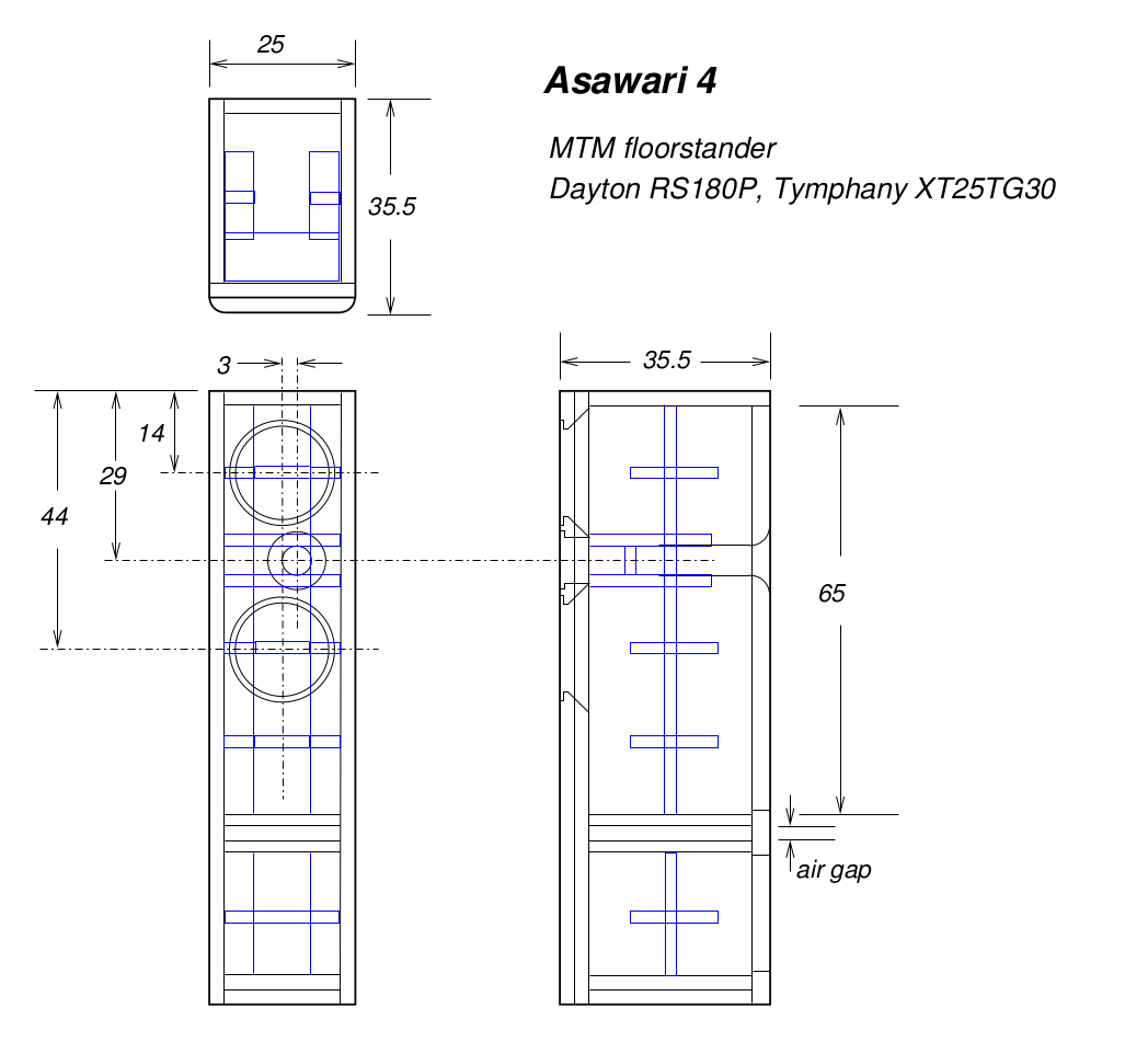
The enclosure is straightforward, identical to the Asawari Mark IV. Basically, with a bass reflex design of about 30 litres of volume, and a port roughly 7″ long and 2″ in diameter, you can get a tuning in the mid-30s Hz and that makes for a decent bass response for this sort of MTM.
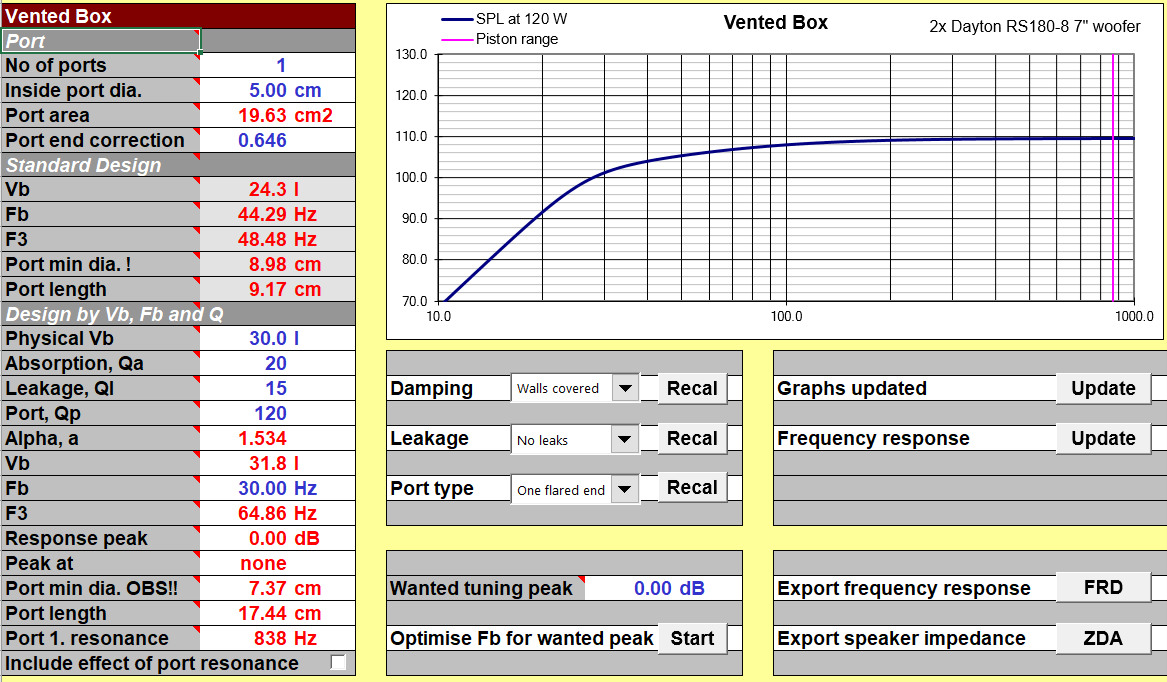
This Unibox screenshot show what I’m working with for the enclosure volume calculations. It’s a 30 litre enclosure, the port diameter is 2″ (see the “5 cm” in the top left of the image), and the port length too is given (see “17.44 cm”) somewhere in the bottom left portion of the screenshot. The curve I am getting extends the low frequency response in a shallow curve for some distance, allowing the room modes to compensate for this slow fall with its own slow rise, thus (I hope) giving me fairly even in-room perceived bass response till about 30Hz or so.
I realised that 30 litres is too small to fill a floor-stander MTM. Therefore, I decided to partition the enclosure into two chambers, one with the drivers, and the second as a dead area at the bottom. This way, I got 30 litres behind the drivers even though the box had an overall volume of more like 45 litres.
The enclosure drawings below all mention Asawari Mark IV, not Mark V. This is not a mistake. The enclosure designs are identical. So is the text describing the enclosure, repeated here for your convenience.
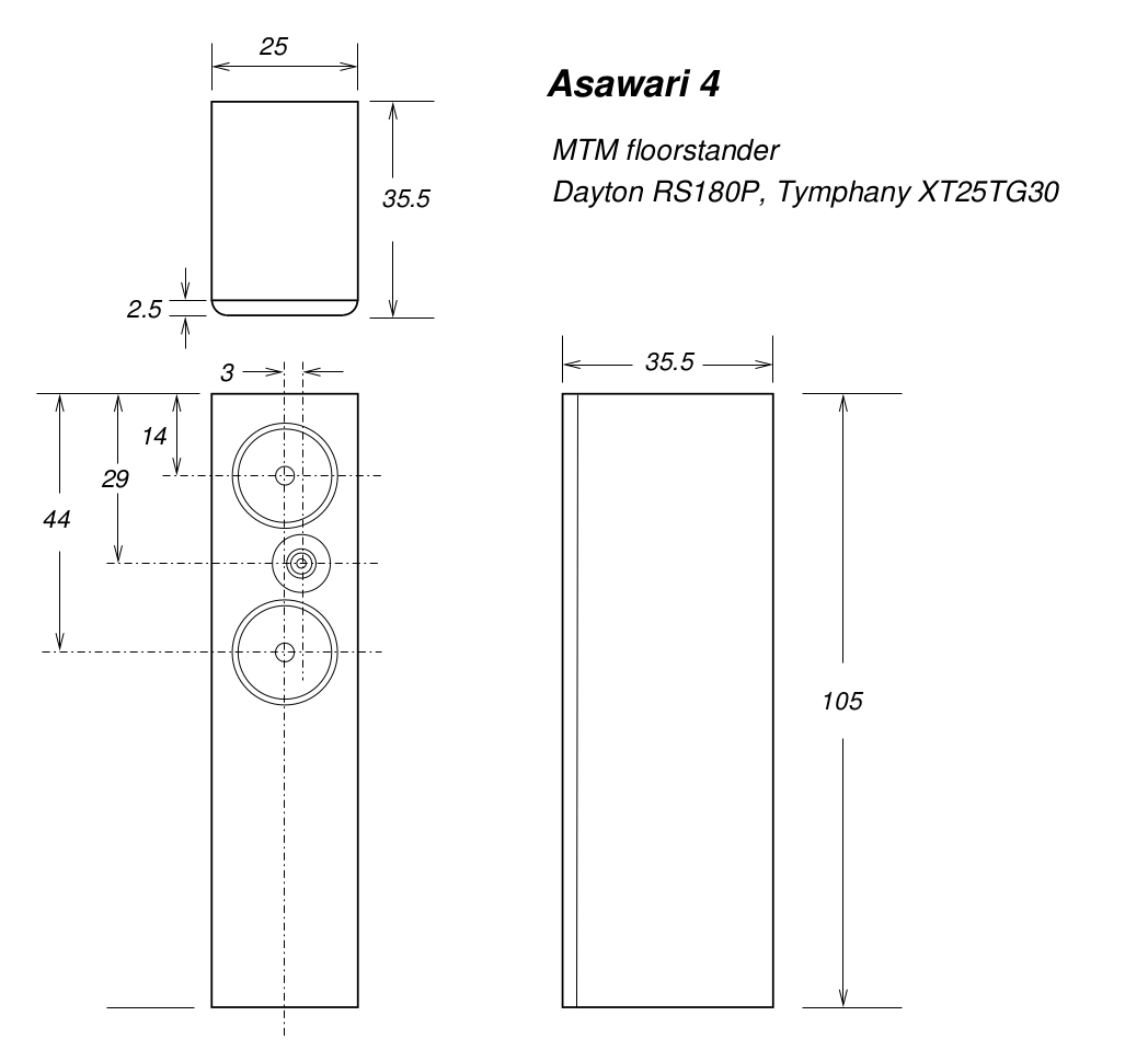
All external surfaces are 25mm MDF. except the outer sheet of the front baffle, which is BTC teak. All internal partitions and braces are 18-20mm commercial ply. I have been following this structure (with or without the BTC baffle) happily for some time now. The front baffle is made of two sheets, making a solid, vibration resistant, 50mm thick inert front baffle. The two sheets are joined together with Araldite to make them literally one solid block.
All braces are joined by inserting screws edgeways from outside, as well as Araldite. The screws are mandatory to pull the walls tight against the braces initially, when the Araldite is fresh. Once the Araldite sets, of course it has tremendous holding power. I have used just Araldite for fixing the braces, and it doesn’t work, as happened with the Darbari. For some reason, I use stainless steel screws for my construction, because I don’t want them to change due to ageing and rusting. (If you’ve ever removed an old, rusted, mild steel screw out of furniture, you’ll understand my feeling.)
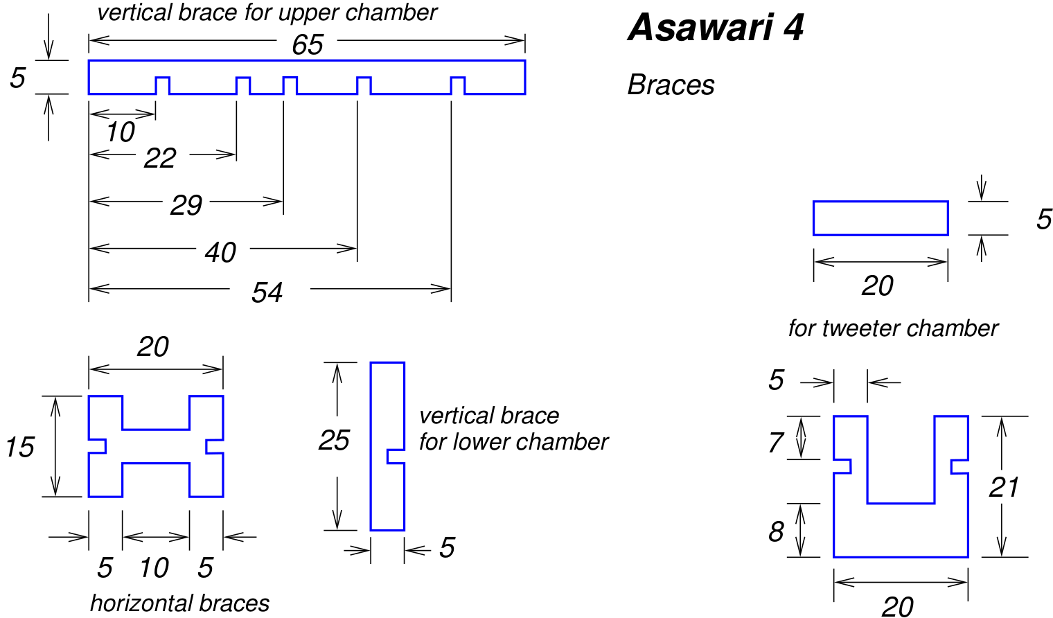
All braces are made out of 20mm plywood, as mentioned earlier.
The tweeter has a separate sealed chamber to protect it from the backwave of the midbass drivers, just in case that vibration results in any tiny vibration of the tweeter body and smudges the soundstage.
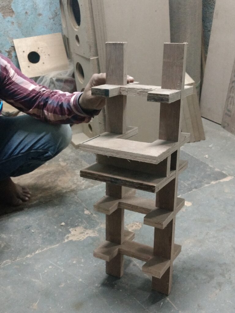
The photo below shows the internal bracing of just the upper chamber. The internal bracing structures are built first.
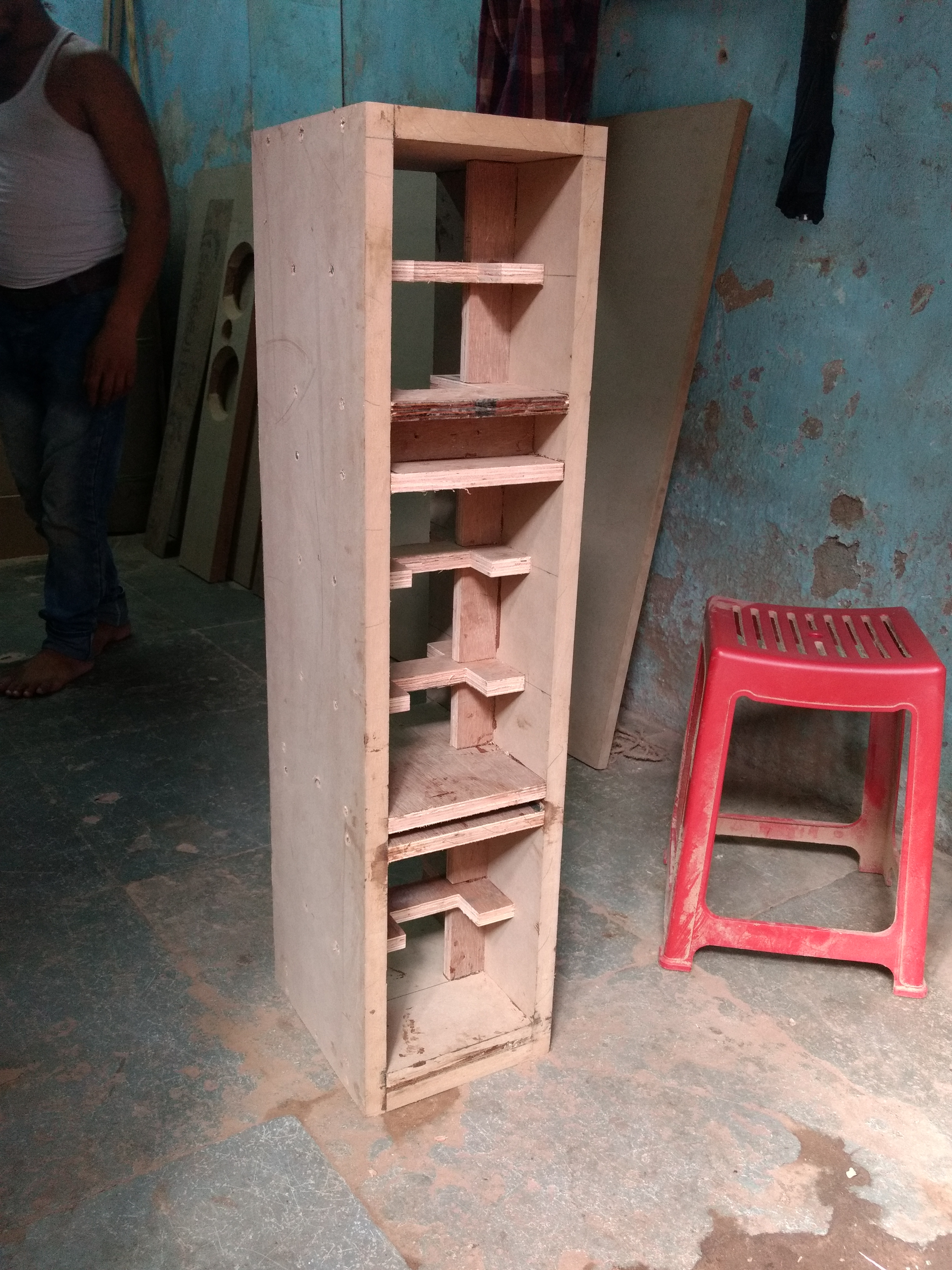
Then the bracing is fitted inside the shells to make the complete enclosures. The front and rear baffles are fixed last. Below is an enclosure with the bracing fitted, but before the front and rear baffles have been added:
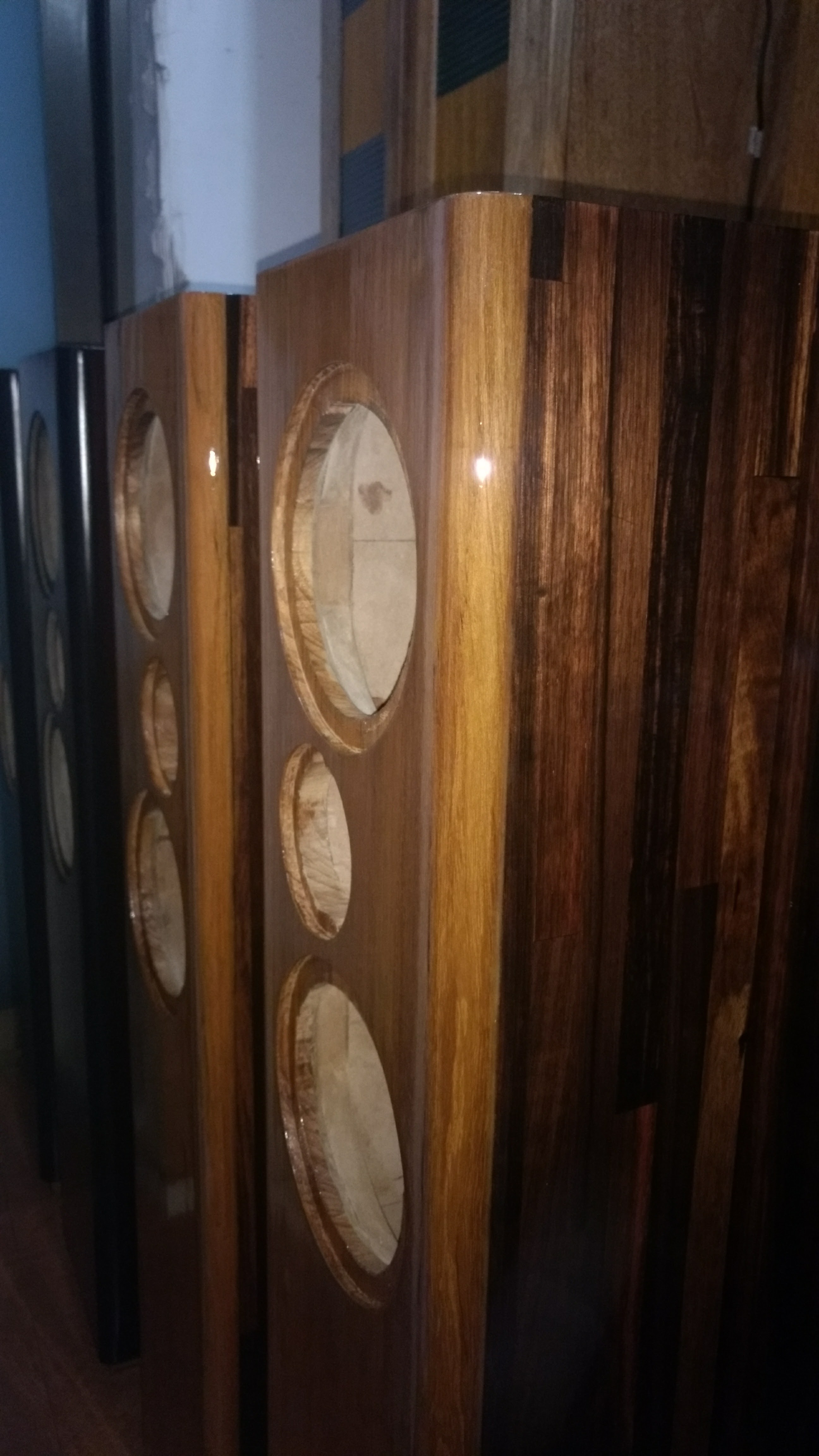
Finished enclosures after polishing but before driver fitting:
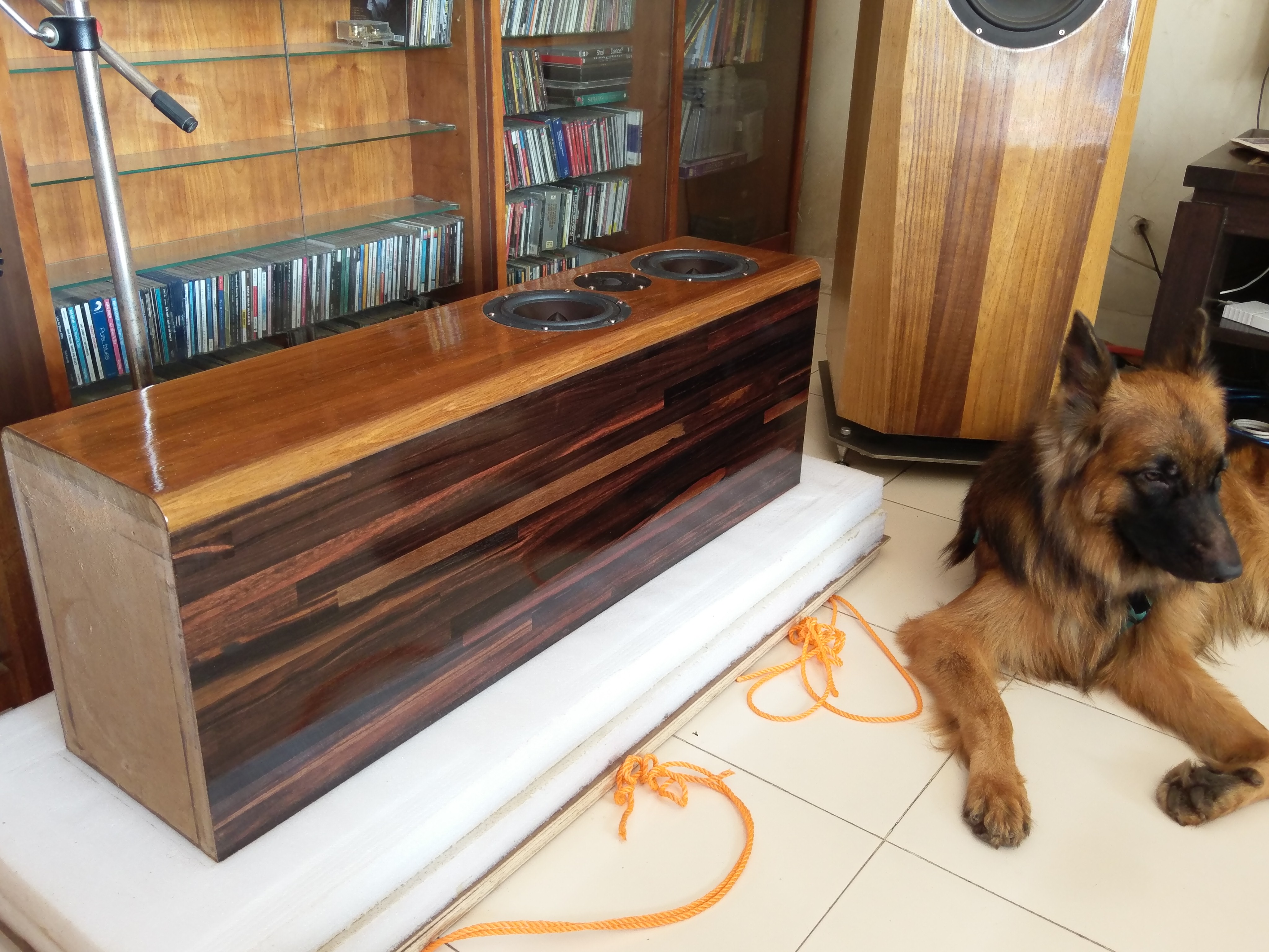
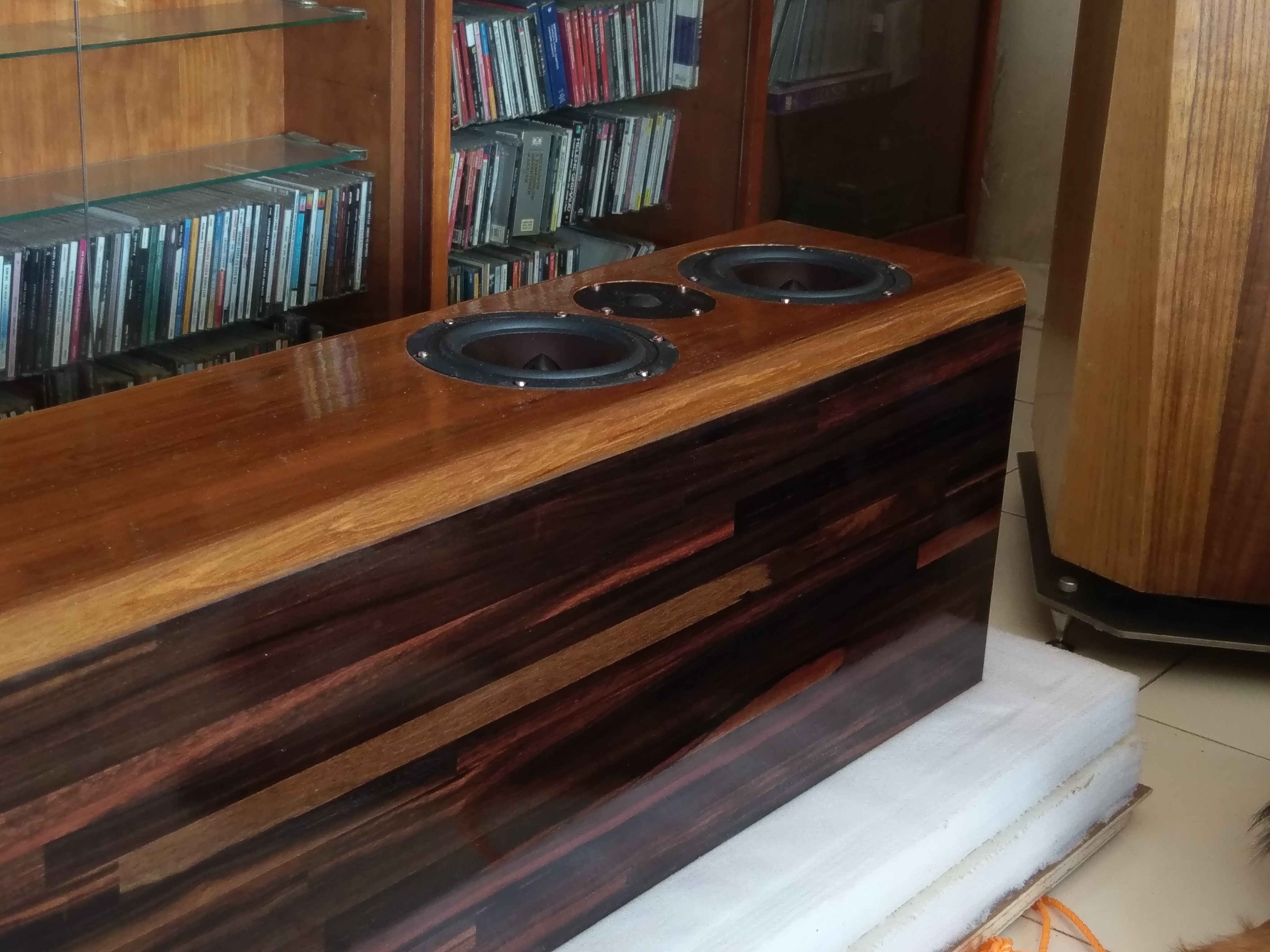
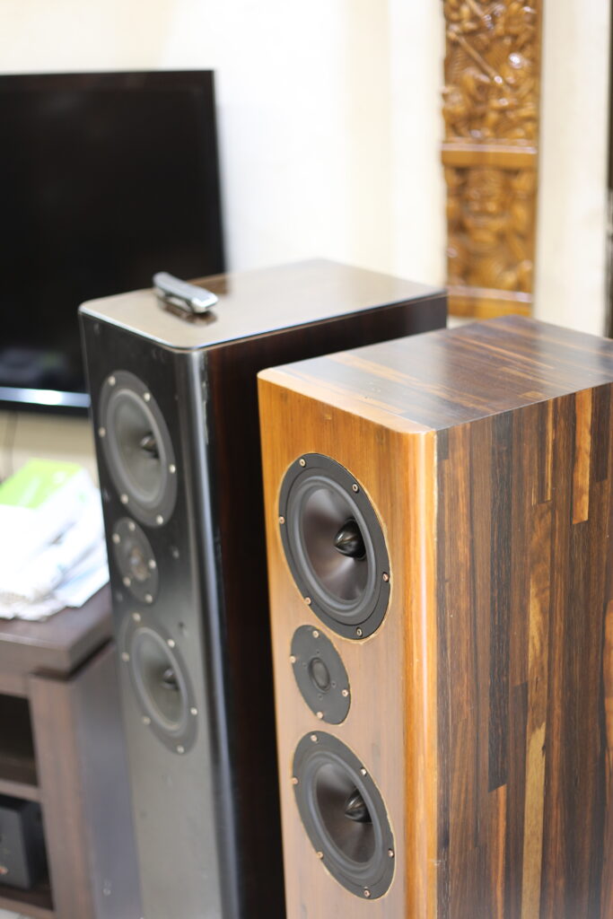
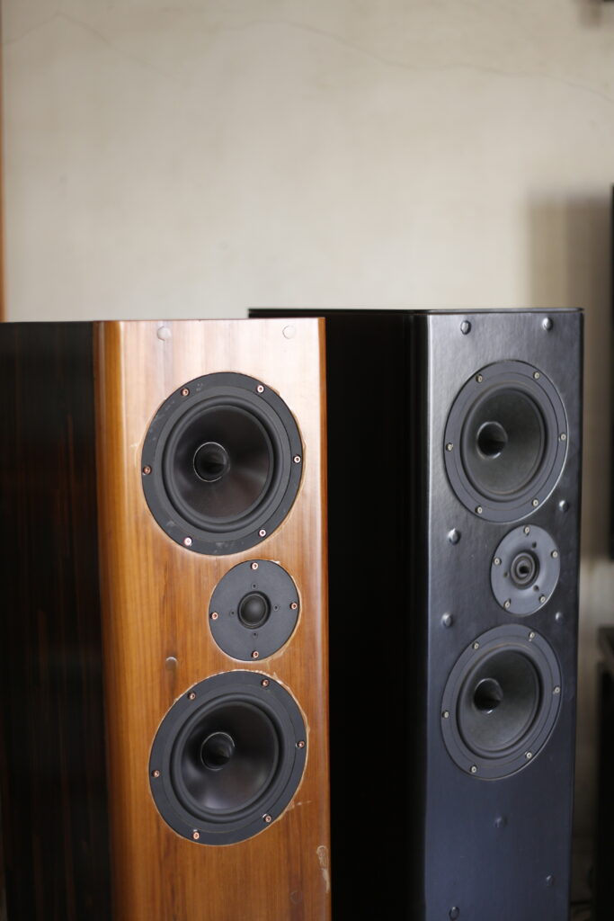
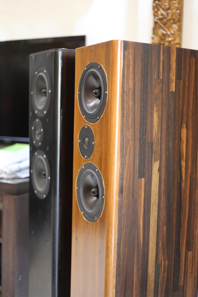
Some photos of the enclosures after drivers were fitted, but before the crossovers were built. The Darbari can be seen behind the Asawari.
The finish has turned out to be very attractive. As mentioned earlier, I built the front baffle with two sheets of material, but for this one, I decided not to use MDF for the outer sheet — I used a 1″ thick sheet of good quality teak wood instead. The sides are finished with real-wood veneer. The finishing has been done with PU polish with 5 coats of sealant applied before the final PU coat was applied. Since I used glossy PU on this one, the veneer patterns are very visible and eye-catching.
Some more photos of the Asawari IV and V.
The crossover
Crossover design starts by taking measurements of the drivers fitted to the enclosures. These were what the raw drivers looked like when measured. Note that these measures do not include anything meaningful below about 700-800Hz, since I only took gated farfield measurements, so that I could design the crossover.
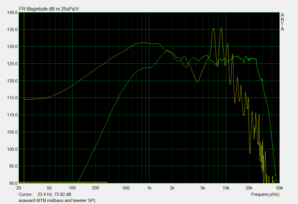
I don’t need to explain it, but the yellow line is the midbass driver SPL, and the green line is the tweeter SPL. The nasty cone breakup of the midbass starts with a big dip at 4KHz, and then show nasty twin peaks at about 7KHz and 8.5KHz. If that portion of the midbass output is remotely audible, it will colour the sound badly, so the aim of this crossover will be cut it as much as possible.
I set my measurement apparatus to operate at 96Ksamples/sec, which gives me measurement bandwidth till 48KHz. Therefore one can see how the drivers behaved at ultrasonic frequencies here. The tweeter rolls off beautifully above 20KHz, without any jagged edges or dome breakups — no wonder it is highly regarded. The midbass drivers continue their jagged cone breakup behaviour right out to high frequencies, which of course don’t bother us because we will be cutting all that region very strongly down using our lowpass filter.
Out of this set of measurements came this crossover after much trial and error.
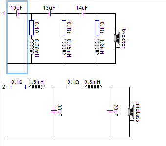
It’s a straightforward fourth-order electrical crossover for the midbass and sixth order for the tweeter. Note how the tweeter is connected in inverse polarity to the midbass. Ignore the blue box — it’s an artifact of how VituixCAD v1 (which is obsolete) displays the crossover schematic. Also do not allow the resistors beside the inductors to confuse you — that’s how VituixCAD v1 used to display the DC resistances of coils. In reality, those resistors are not separate components when I build the crossover — they are just internal DC resistances of the copper of the coils.
This schematic gave the following final SPL curve:
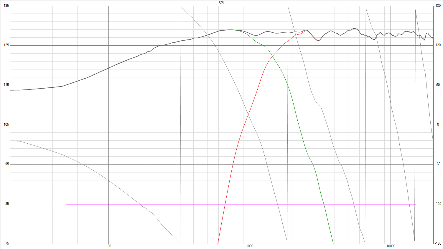
It’s interesting to see where the twin peaks from the raw SPL curve have gone. In the raw SPL curve above, the peaks were very prominent and were far above the base SPL level. After the crossover, the graph shows only about 50dB of dynamic range, therefore we can only see things which are about 50dB below the baseline. We see that the green line of the midbass SPL curve drops by about -50dB at about 4KHz, in quite a steep slope, and we can expect that this slope will continue indefinitely. Therefore the twin peaks which were there at 7KHz and 8.5KHz will be at least 70-80dB below the base line. This is the entire purpose of the higher-order crossover I’m using here.
As one can see, the crossover point is about 1.5KHz.
Another thing visible is that the crossover is effectively 6th order acoustic, even though we have used 4th order electrical on the midbass driver and have achieved the steep slope. 6th order acoustic means about 36dB/octave slopes, and also says, as per the textbooks, that one of the drivers will need to be connected in reverse polarity to get the summed SPL to be flat. This is what we are seeing here too.
And the impedance of this crossover is as shown:
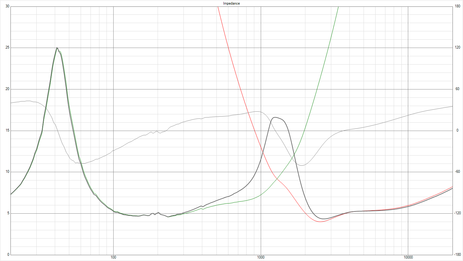
This is a solid 4 Ohm design, as was expected from the time I decided to choose two 8 Ohm midbass drivers and hook them up in parallel. Really low-power solid state amplifiers like LM3875 Gainclones may not be able to drive this speaker to its best performance. As always, ignore everything in the impedance curve below about 100Hz, since the impedance measurement does not show what the reality will be. This impedance measurement was done before the bass reflex port was fitted and the enclosure filling was done. The final impedance at the low end will be impacted by all that.
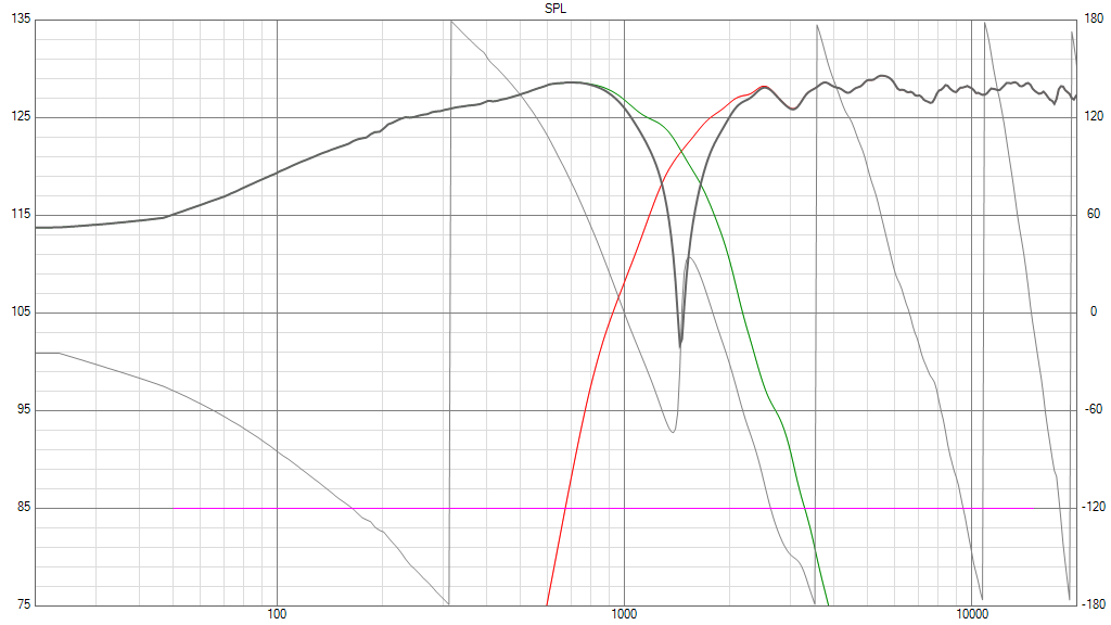
To test the phase alignment of the tweeter and midbass drivers, there is the convention of reversing one of the two and seeing if the SPL shows a deep reverse notch. That is shown here:
In case you are interested in the modelled group delay and phase behaviour of the crossover, here is the graph:
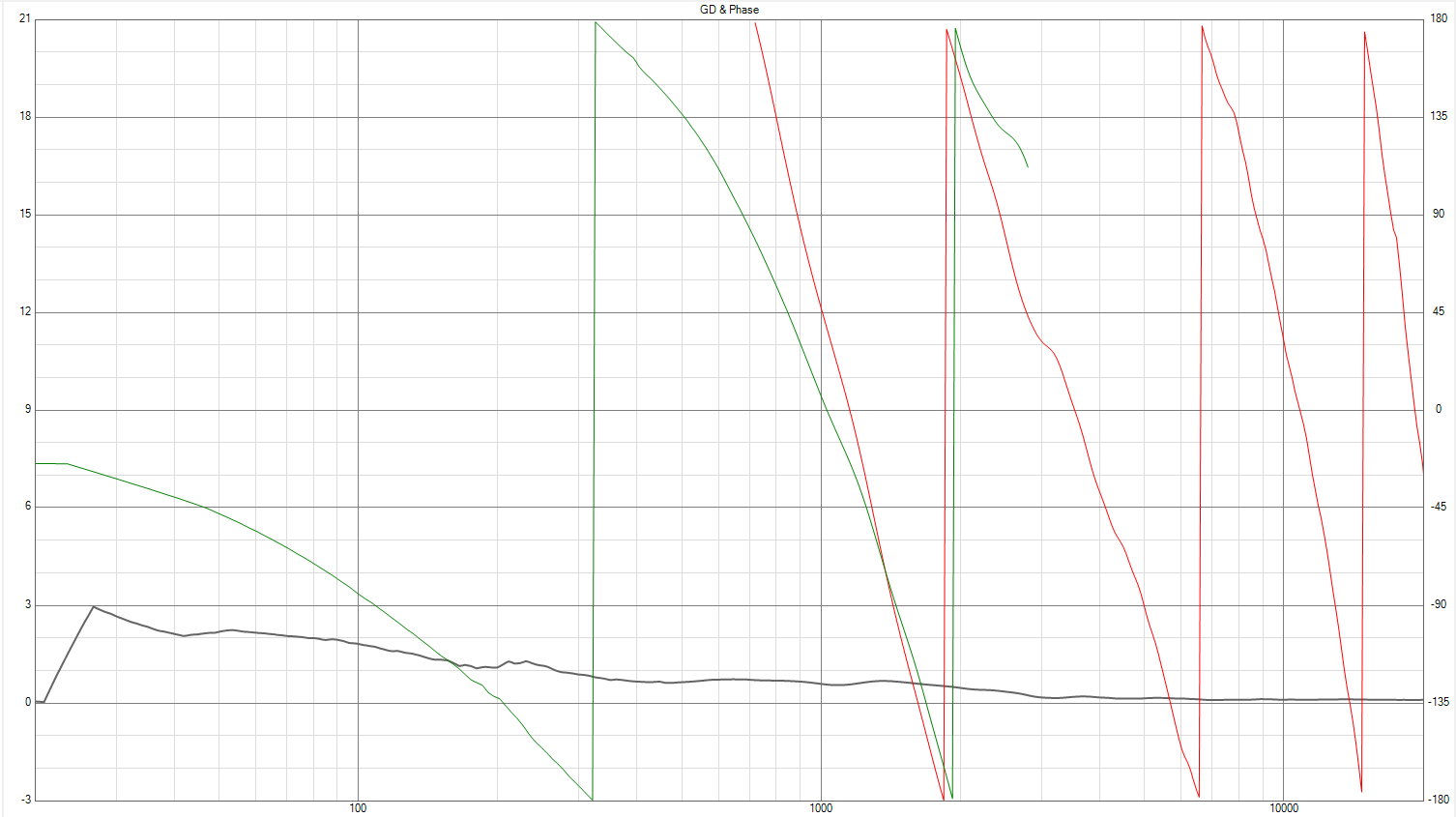
It shows that at low frequencies, the output of the speaker will be delayed upto a max of 3 milliseconds from the rest of the frequency response. This is a reasonably good figure, though I am not sure how much this will match with in-room reality. The data here does not include the port output, which will have its own group delay.
How does it sound?
I put it together (my first sixth order crossover, lots of parts) and did the usual tuning of absorbent material behind the midbass drivers, added a baffle-step compensation at the input to the crossover (please read the details in the page on the Asawari 4), and finally sat back and listened.
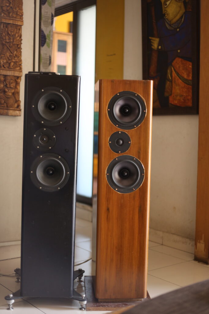
I had the good fortune, for the first time in my life, to listen to two pairs of similar speakers in the same room at the same time: the Asawari 4 and this one. It was, for me, a huge milestone, a big set of insights. Needless to say, I am sure that more prolific and experienced designers have learned this a long time ago — I was learning it about 15 years after my first mature design (the Asawari Mark 1).
I learned the following:
- Both the speakers sounded tonally balanced, but had quite different “flavours”. Absolutely no doubt.
One friend (a music lover with ears 30 years younger than mine) said that upper mids and treble seemed to have been turned up slightly in the Asawari 5, as if with tone controls. This is not true, but I know exactly why he felt this. He was one of the contenders considering picking up one of the pairs. He took the Asawari 4 — shipped them to Delhi, and has been a happy user ever since.
Another close friend came over to listen to both pairs. He’s an experienced speaker designer from Pune, who has built more speakers than I have. He likes classic rock (and other rock) a lot. He heard both pairs, and had difficulty picking one. He finally concluded that the metal-cone Asawari 5 had the edge, so he took them. - The paper-cone Asawari 4 sounded more rounded, the Asawari 5 sounded more etched. I am led to believe that most audio lovers consider paper cone sound “more natural”, but I did not think so. I also told that they consider metal cone sound to be “etched, bright, with a kind of glare” but I agree with those words strictly in comparison to the paper-cone flavour. I wouldn’t say this in isolation.
- My comparison could be a reflection of the tweeter difference, the crossover difference, etc, so I’m not insisting that all the differences were due to the midbass cone material.
- The flavour difference is a matter of taste. I personally will give the metal-cone cleanness and sharpness a few extra marks if I have to pick one. There is genuinely less distortion, more cleanness, less time smearing, with the metal cones. But there is a different kind of HF ringing with them which is impossible to eliminate even with my super-steep 6th order slopes.
- Like all Asawaris before this, the Mark IV and Mark V too do not handle Rhydhun’s “Jiji-rhy” or Guns’n’Roses’ “Paradise City” convincingly. Don’t try those stunts on these speakers, or any other 2-way. This is one big reason why I build the Darbari, and why I’m doing a lot of 3-ways now.
One more thing I learned, unrelated to sound quality:
- That BTC teak front baffle, together with glossy PU finish, makes for something truly eye-catching. Slurrp.
Update 2025: What next for the Asawari?
At the time that the Asawari 4 and 5 were being planned, SB Acoustics were just beginning to emerge. What a range of models they bring to the table — they are a DIY experimenter’s dream. Look at the variants of their 6.5″ midbass drivers:
- SB17NRX: coated paper cone, but far stiffer than paper cones of 25 years ago
- SB17NBAC: aluminium cone, but with lovely radiating ridges on the cones, to defer the onset of cone breakup and make them far easier to work with than the RS180. What I need a 6th order for in the Asawari 5 will be possible, I think, with a 4th order with the SB17NBAC. I love it.
- SB17CAC: ceramic coated aluminium cone. Better damped than the NBAC, with the same light weight, low distortion and stiffness. Better damped means reduced cone breakup. I’d choose the CAC over the NBAC any time. Same 4th order rolloff will give me cleaner sound without losing anything.
- SB17CRC: carbon fibre, ladies and gentlemen. This is the space age (well, 20th century space age) alternative to paper cone. It has superior lightness and stiffness but without the aggressive cone breakup of pure metal cones. All my research tells me that just like I’ll choose CAC over pure-metal NBAC, I’ll want to choose CRC over pure-paper NRX.
- Satori MW16P: top end low distortion paper cone. The pinnacle of what a driver designer can do with paper cones.
- Satori MW16TX: the pinnacle of midbass drivers, to compete with the best in the universe. All the distortion reducing and noise reducing measures mated to a 21st century Textreme cone. The absolute SOTA for the combination of low mass, high stiffness, excellent damping, minimised cone breakup. If you are the speaker-designer equivalent of those who only fly in private jets, not commercial, then this is the driver you’d pick.
I see at least a couple more Asawaris down the road. One with the SB17CAC and probably the SB26CDC, another with the SB17CRC and maybe the SB29RDAC. Maybe I’ll retain everything else about the Asawari DNA but make them 18″ standmounters this time. And I’ll listen to them side by side and log my findings here.