(Originally written in 2013. Project was started with initial design and procurement of parts in 2008, was completed in 2014, and was used till 2018.)
Design notes
I wanted to build something better than the Asawari for my own use. I wanted something which would allow me to stretch the performance envelope and force me to learn new insights into speaker design. And I called it the Darbari in memory of the original Dagar Brothers, whose 1973 performance of the Darbari Kanhra for HMV is still a legend (never published on CD).
Three’s company
I decided that one of the first steps forward was to move from the undeniable compromises of the two-way to the three-way speaker. The two-way speaker has the difficult task of delivering punchy bass and delicate, nuanced voices through the same driver. Imagine one cone moving in and out, in and out spasmodically to the beat of a big bass drum, and at the same time trying to vibrate in delicate ways to generate frequencies of the human voice. It’s a crazy demand, and drivers usually do not do a very good job with it.
Therefore, one challenge the speaker designer has to take is to keep aside a separate driver for the two bottom octaves, up to about 80Hz.
Regarding this issue, there is one audiophile and DIY myth that comes to mind. There is this strange belief that the human voice stretches from about 300Hz to about 3KHz. Many a speaker designer has tried hard to keep this range of frequencies within one driver, so that the polluting effects of a crossover do not hit this most special of frequency ranges. The truth is that a male voice often has a fundamental frequency at 150Hz, and female voices often start from 250Hz or so. Therefore, if one has to reserve a single driver to handle the voice frequencies, this driver must stretch from 100Hz to about 3KHz.
The right way to do this would be, of course, to use a wide-range or so-called “full range” driver. and add assistance to the top and bottom ends. You need an extended-range driver which can handle the range of 100Hz to at least 4KHz smoothly. There is probably no better driver for this role than the Jordan JX92S or its successor the the Jordan Eikona, if you can afford it. I have lived with the JX92S for a few years in a single-driver enclosure, and I’ve seen very knowledgeable designers compare this driver with other similar-sized drivers. There is really nothing from Scan-Speak or other major brands which can beat the JX92S as an extended-range midrange driver. Those who have tried to describe the sound of the JX92S have used the phrase “electrostatic-like”. You have to hear it to believe it.
I no longer had access to the JX92S. Nor could I afford one at that time. So, for the Darbari I used a more ordinary midbass driver.
Get active
Another thing I decided to do was build an active crossover system. I wanted to see what I could do with electronics. I had been getting more and more interested in amp design and electronic circuit design, and it would be fun to channelise this curiosity into giving me better sound than a passive speaker. Secondly, I had alread about the benefits of active crossovers. It would be nice to see what a good active system sounds like.
When the bell tolls for me
A third aim was to work with low distortion metal cone drivers. These drivers deliver lower distortion in the bass and midrange regions than paper cone drivers, but have serious stored energy problems in the region of their cone break-up. At the cone break-up point, they often have peaks which rise 15dB above their base SPL, and also resonate, i.e. keep ringing after input signal stops. The only way to get good performance from such drivers is to cut the cone break-up region so aggressively that they do not have any audible effect on the sound. This is very difficult to do.
Conventional crossovers with fourth-order slopes just do not deliver the goodies. They will do a fine job with a metal-cone woofer if you want a 100Hz low-pass and the cone breakup is at 1KHz. But if you want to use a metal-cone midbass driver, then you will want to take the midbass up to about 2KHz, and the cone breakup will rear its head quite close by, at perhaps 4.5KHz. You will then have little over one octave to bring down the SPL by at least 80dB.
Many conventional speaker designs using the excellent Seas Excel range of midbass units have tried mating a notch filter with an LR4, in a passive crossover. This was, in my humble opinion, very difficult to do. You need a wide, i.e. low-Q, notch, since the cone breakup gives rise to a cluster of multiple peaks, and you have to cut the whole bunch. Getting a deep, low-Q notch to work well with a passive crossover is not very easy.
Some designers, including the very respected John “Zaph” Krutke and Joe D’Appolito, have been happy to cut the resonant peaks by 30-40dB for some of their speaker designs. The Seas Thor kit is an example of this sort of crossover. In my humble opinion, a cut of 40dB is simply not enough for this malaise. This is no benign second harmonic distortion, where some audible distortion can make the music a bit more euphonic. This is true ring-like-a-bell resonant ringing, of the kind that can slice your ears off with listening fatigue. Cutting these down by merely 40dB will not make good quality speakers.
The only good treatment of this disease that I read about was the Modula MTM built by Jon Marsh in the “Mission Accomplished” DIY forums of www.htguide.com. There, he designs an MTM using metal-cone midbass drivers and crosses them over to the tweeter at a low 1,400Hz. And above 1,400Hz, he cuts the SPL with a Cauer-Elliptic passive crossover which starts out looking like a fourth-order and then steepens rapidly to an eighth-order slope. Only with this sort of all-or-nothing approach will a designer be able to make the ringing truly go away.
That was my aim too, but with active filters. I intended to build an LR4 low-pass, followed by a notch filter. Simulations of this topology with a metal-cone midbass driver’s FRD and ZMA files have yielded SPL and phase results very close to the Cauer-Elliptic, and Jon Marsh had approved. I had built nothing physically at that time, but this time I decided to bite the bullet.
My aim was very clear: the highest peak of a cone-breakup resonant spike in the SPL graph must be brought down 70dB below the flat base level of the pass-through portion of the SPL curve. Basically, there should be no portion in the breakup region higher than -70dB below the base SPL level.
Why struggle with metal-cone drivers at all? Simple: they have rigid cones, and these generate less distortion than any floppy-cone drivers, e.g. paper or poly cone drivers. Those designers who wish to keep simple crossovers use soft cone drivers because these drivers have smooth and benign SPL curves and can be mated easily with other drivers in a crossover. No cone breakups and nasty jagged edges to tame. But what you gain is a lot more low-order harmonics. Many listeners actually don’t mind those harmonics much because they are often second-order and add a certain warmth and richness to the music. If you want to see one veteran designer’s honest assessment of his recent 3-way design with a paper-cone midrange, check out Roman Bednarek’s JDB3 and scroll down to the section titled “Listening Impressions.” That analysis sort of captures it all.
But I wanted low distortion sound, and I wanted to learn to tame the beast of the tolling bell.
Configuration
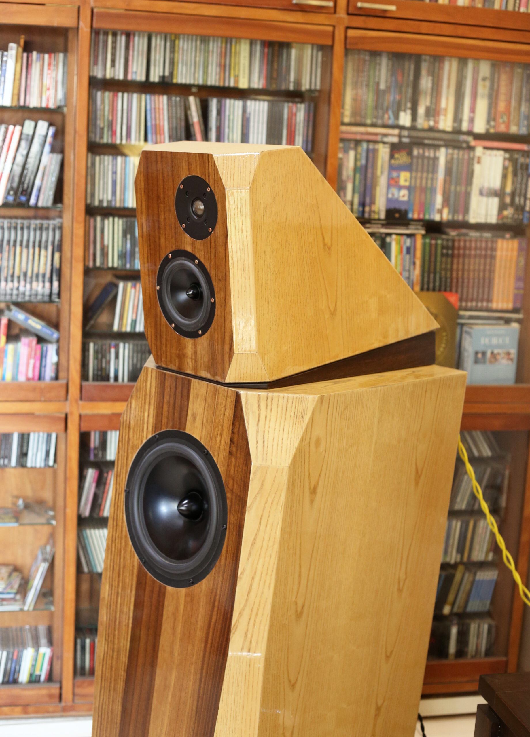
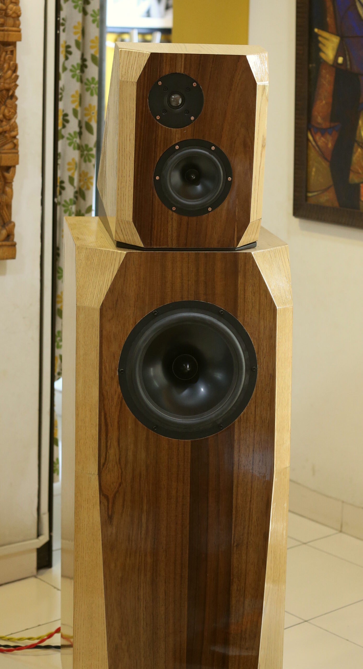
I therefore decided to build a three-way, but I did not want to go the sat-sub route. I would prefer to build a floorstander. I aimed for a sealed bass enclosure with a woofer handling the sub-100Hz range. (It later became 150Hz.) On top of this would be a separate mid-and-tweeter enclosure, physically separate, so that baffle vibrations from the woofer enclosure do not communicate to the mid-and-tweeter unit. I thought of placing a soft mat, like a folded towel or a felt mat, between the two enclosures, and placing, not fixing, the mid-tweeter enclosure on this mat.
I wanted to model the enclosures in shapes inspired by Neil Patel’s Avalon speakers. Flat surfaces, bevelled corners, front baffles three inches of solid MDF, and of course, the extensive internal bracing as per the tradition first used with the Asawari.
And I wanted to build stereo amps in separate chassis, so that my curiosity about amplifiers would be catered to as well. I thought of building amps in re-usable blocks, one stereo power amp per chassis, and swap amps in and out. I finally used a six channel home theatre amp to drive the Darbari.
Drivers
I decided to use a trio of drivers which were well-known as being low distortion and excellent value-for-money.
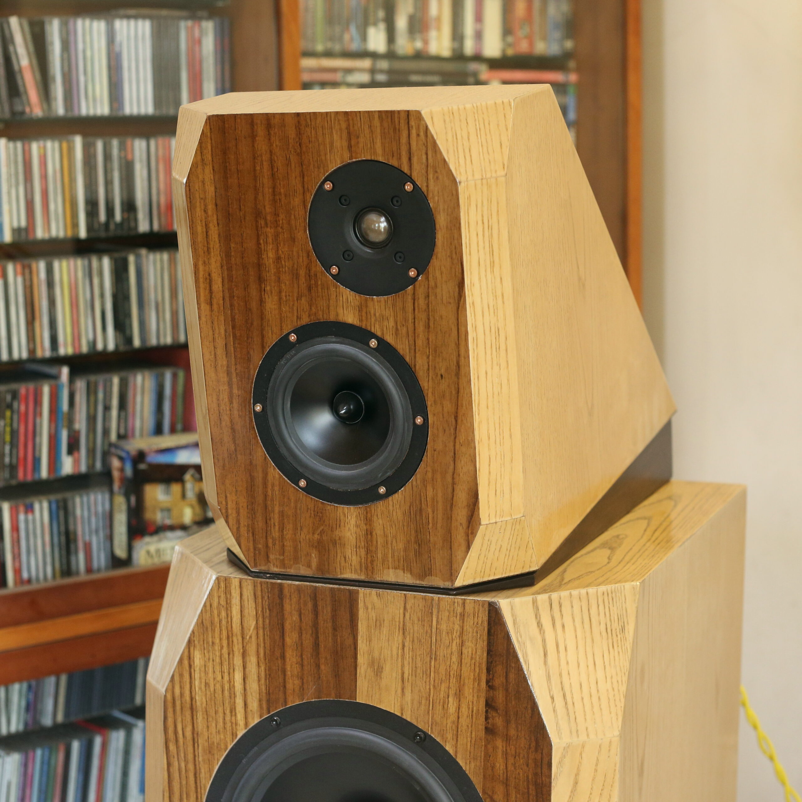
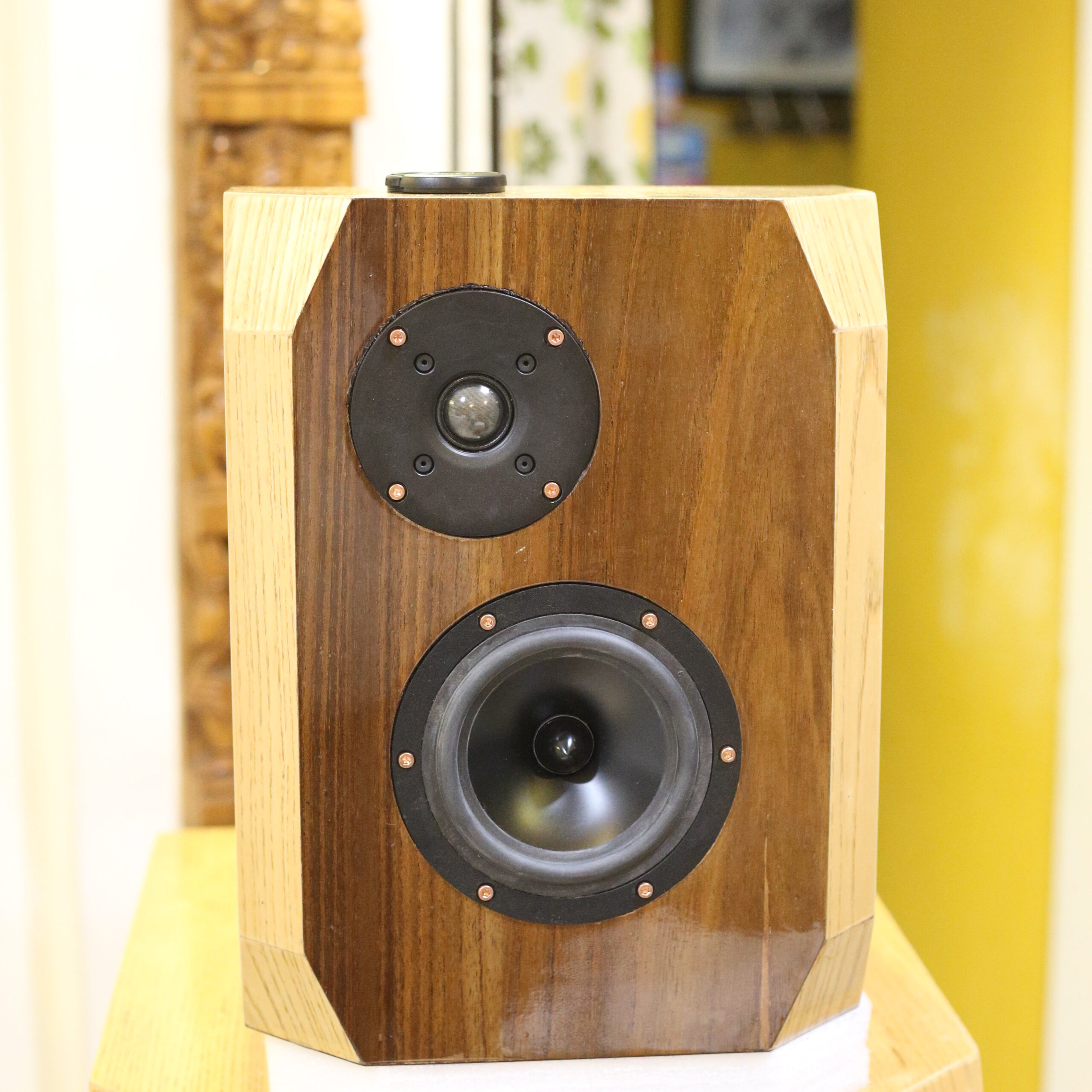
The tweeter: It was originally planned that this would be the Seas TDFC fabric dome tweeter. John “Zaph” Krutke confirms, in his tweeter tests, that this is one of the lowest distortion tweeters around. A lot of boutique tweeters costing twice to four times this little thing actually have higher distortion. A second lovely feature: this tweeter can be crossed over quite low. That was a necessity to let me tame the midbass beast.
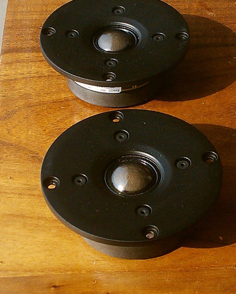
I later read that the Peerless 810921 is an even lower-distortion tweeter. It’s about 50% more expensive than the Seas TDFC. I decided to switch to this tweeter, increasing my total costs for the Darbari by about $50 for the pair. The Peerless HDS is now available not under the name Peerless, but as the Scanspeak Discovery D2608/9130 HDS dome tweeter.
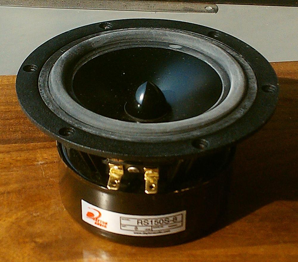
The midrange unit: This was the Dayton RS150 6″ midbass driver. I intended to cross this over to the tweeter at about 1,500Hz or so, so that I got the maximum opportunity to kill its cone-breakup peaks. On the bottom end, this driver would happily deliver 80Hz and below, hence I thought that I would be able to get it to deliver a Qtc of 0.7 with a Linkwitz Transform, in a sealed enclosure. All this sealed Qtc proved too complicated and useless, so I landed up doing a straightforward crossover from this to the woofer at 150Hz.
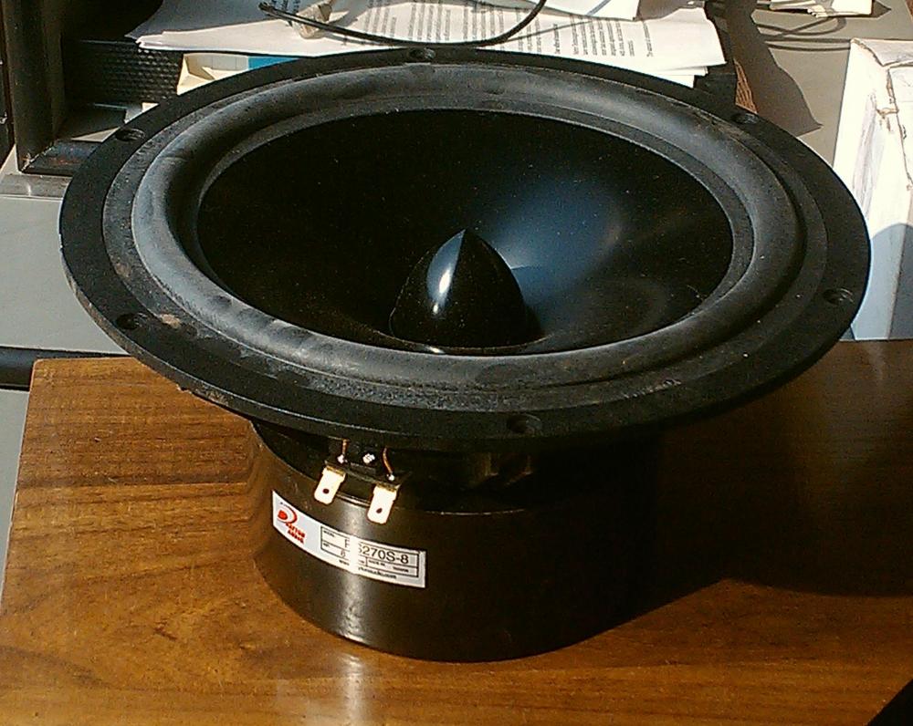
The woofer: This was the Dayton RS270 10″ woofer. I intended to use this from some point below 100Hz, down to about 25Hz, in a sealed enclosure. (I finally landed up using it from about 35Hz to about 150Hz, which proved to be an excellent choice.)
The enclosure
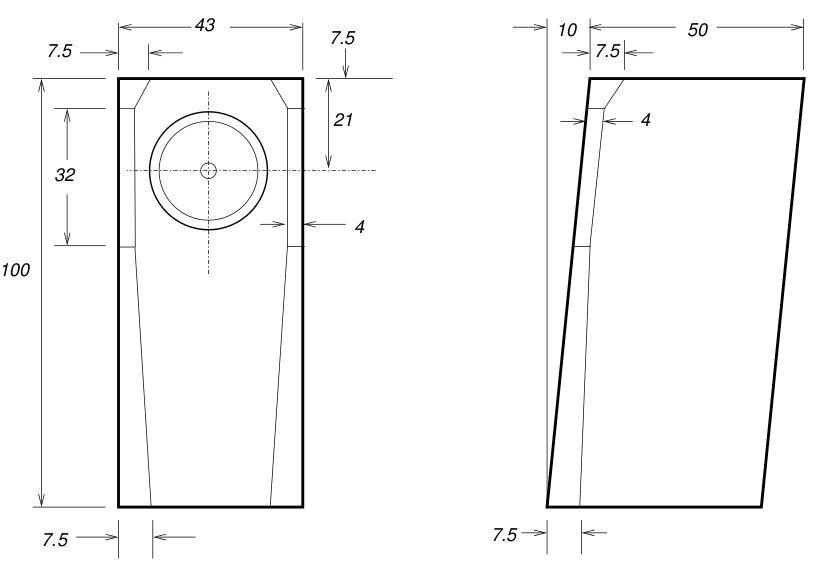
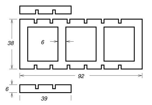
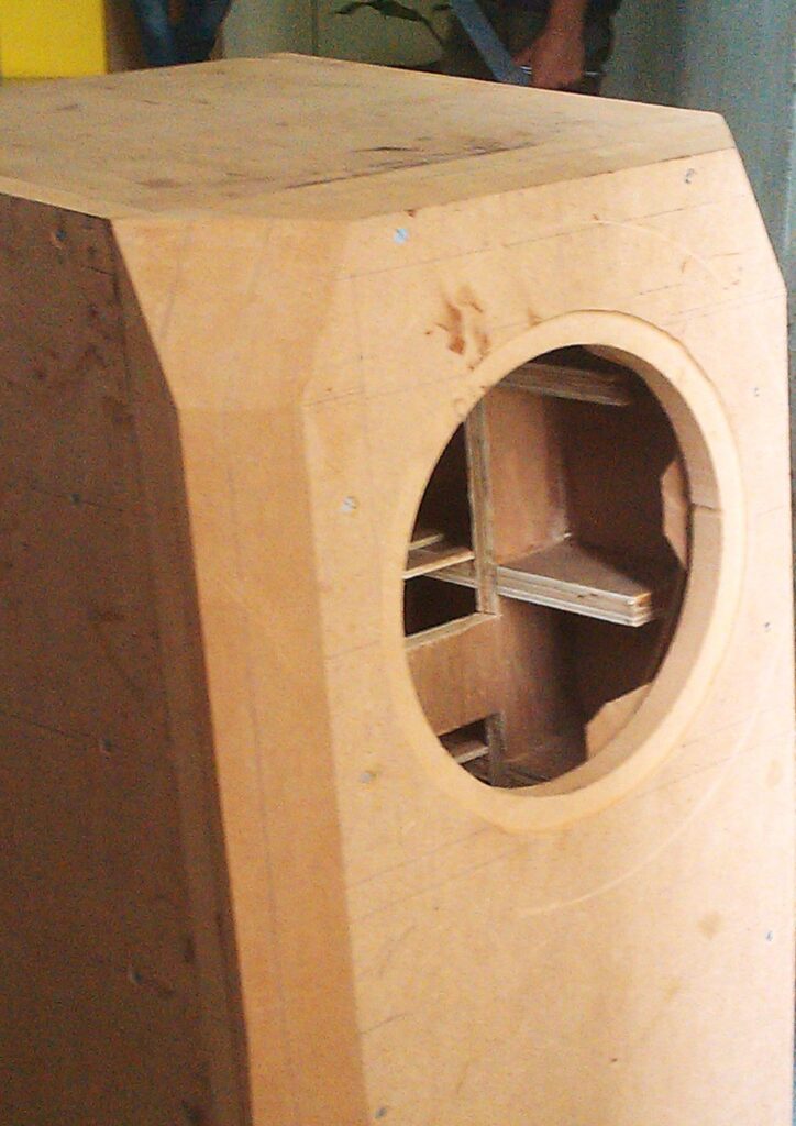
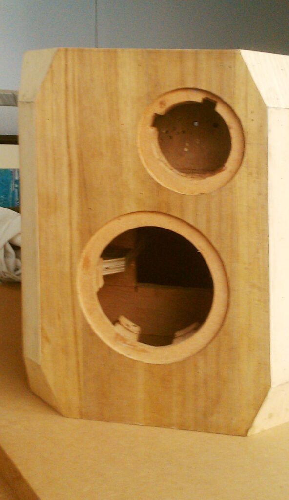
I decided to go for a two-box enclosure design, as shown below. The woofer enclosure is shown below.
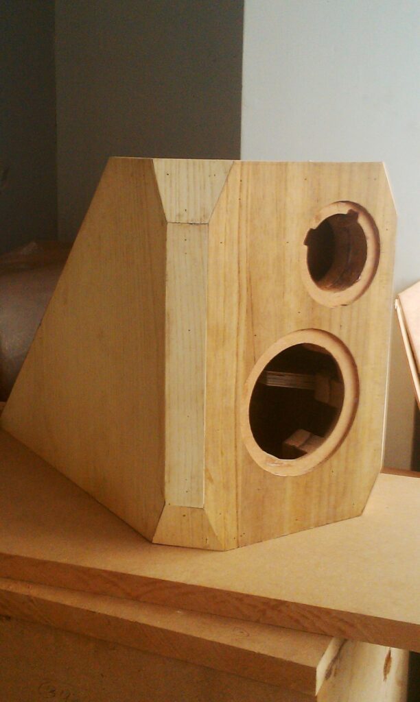
I built a second enclosure for the midrange and tweeter, to be placed on top of the woofer. The upper enclosure looked like this:
The upper enclosure is narrower than the woofer enclosure, but they have the same depth. I aligned the front baffles of the two enclosures and centered the upper enclosure laterally.
Modelling the woofer in its enclosure gave an interesting picture. The enclosure is about 141 litres. Unibox said that this box, sealed, gives a modeled response something like this:
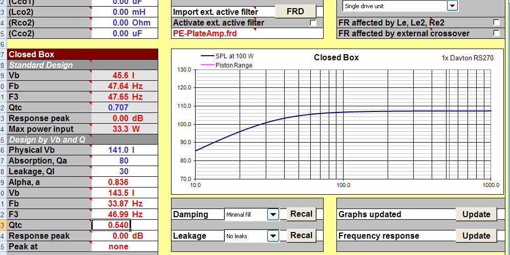
We got an Fb of 34 Hz, an F3 of 47 Hz, and a Q of 0.54. All in all, a beautiful overdamped enclosure which would not give me the deepest theoretical bass but would give me tight transients with no boominess (save that which would be added by room modes).
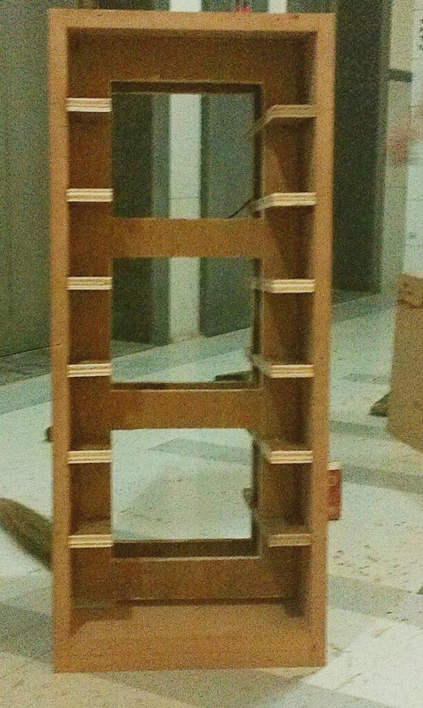
Internally, the woofer enclosure had strong 20mm plywood fitted edgeways to the side walls from the inside, every few inches. Also note the three-sheet-thick front baffle. I prefer very solid front baffles, to ensure that there is zero radiation of spurious vibrations from the front. In the Asawari, I have used two-sheet front baffles, and they have been absolutely dead. Here, partly for greater strength to hold the 10″ woofer, I used three sheets.
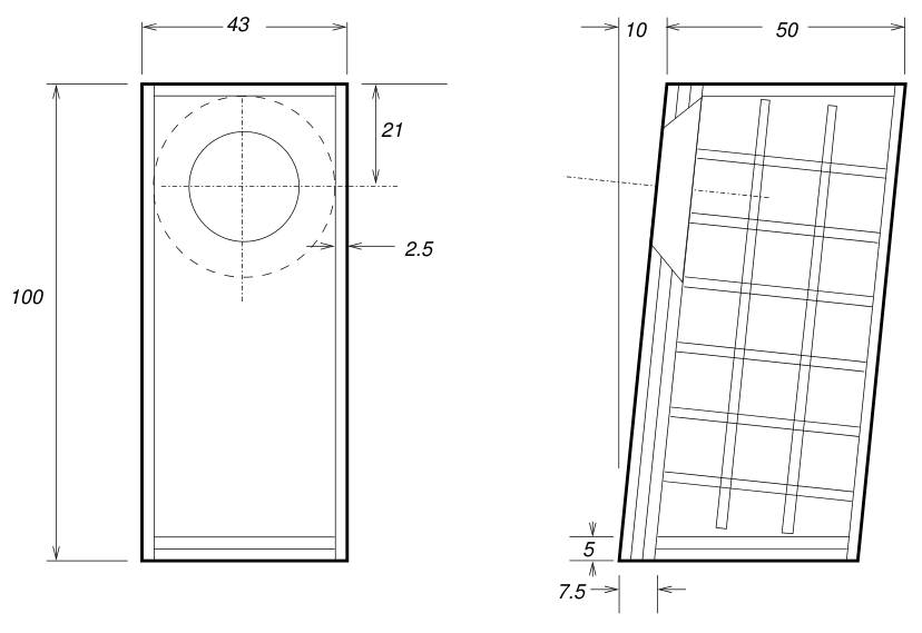
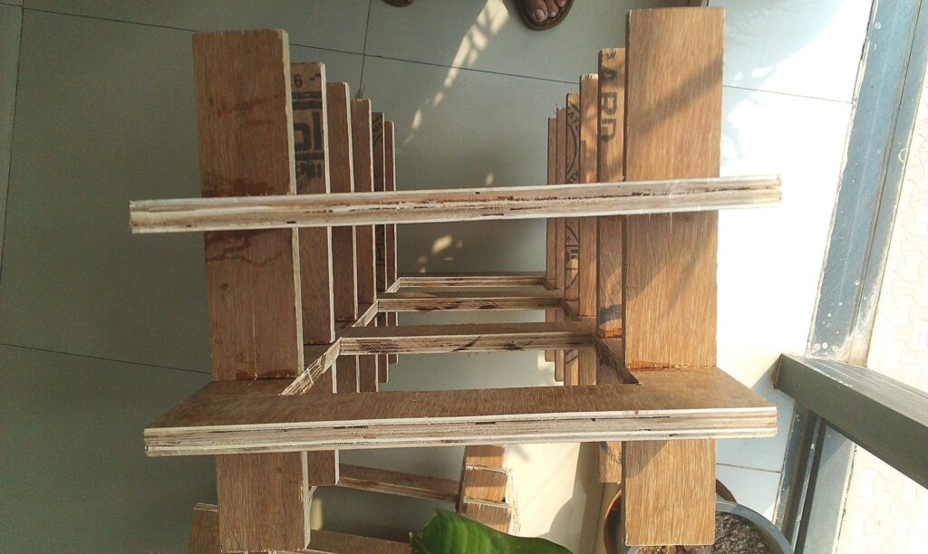
Since the woofer box was fairly large, it became easy to design an internal bracing structure which would be assembled as a separate sub-assembly, with strong Araldite-based internal joins. This sub-assembly could then be placed inside the box, and the walls could be screwed down to the bracing, together with some more Araldite.
So, the internal bracing for the woofer box was made of the following types of pieces:
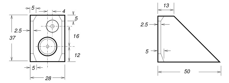
The upper enclosure internals look like this:
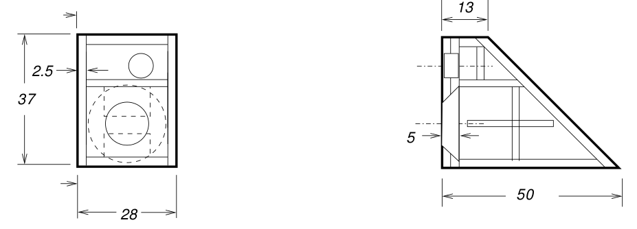
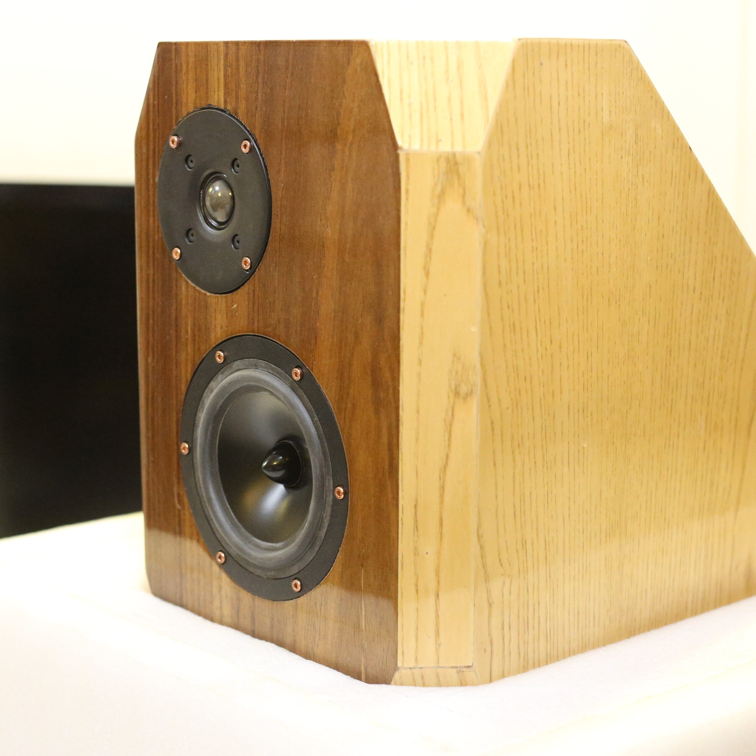
The front baffle had two sheets of MDF. There is a separate sealed tweeter chamber. I started this practice from the Asawari II onwards, once I realised that the tweeter’s front plate vibrates very slightly in the Asawari Mark I, due to the back wave of the midbass drivers.
I used 45-degree cuts on corners and edges to give the enclosures a slightly less boxy appearance. For the tweeter, the cuts also served to reduce edge diffraction.
In the upper enclosure, the back wave from the midrange would be dissipated in the rear of the enclosure and not bounce back to the cone with as much force as in the case of a rectangular box. I intended to fill the midrange enclosure with Dacron fibre only at the two rear corners, i.e. at top and bottom. The rest of the enclosure would be empty.
Building them boxes
Woofer enclosure bracing
The woofer enclosures badly needed bracing, because they (like the Asawari Mark I) had huge side panels which would sing like a drum if they were not braced. Since this enclosure would generate only low frequencies, any bracing which moved the resonant frequency of the side panels to the KHz range would effectively block the vibrations. As per Seigfried Linkwitz, if bracing is applied in a matrix or grid manner where adjacent braces have gaps less than about 4-5 inches, then the resonant frequencies are pushed up to the KHz range. So I intended to do that.
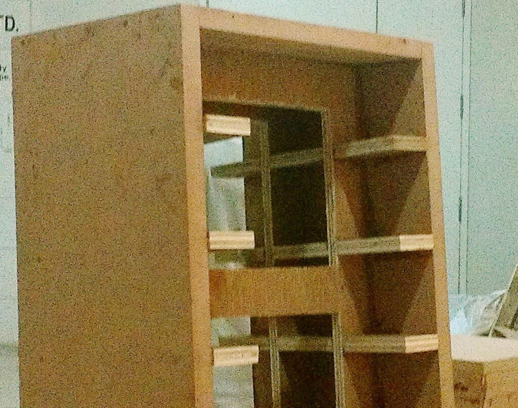
I built the bracing frame as a separate sub-assembly out of 20mm ply (my material of choice for bracing). The pieces were assembled and then joined together with screws and Araldite, one per enclosure. They were almost three feet tall each, and were amazingly strong, rigid, and light for their size. You could lean on them and lift your feet off the ground, and they would take your weight but would not bend or tilt at all. I tried it. Quite satisfactory.

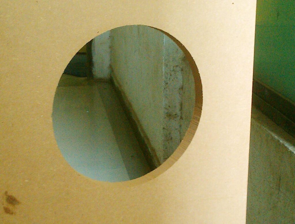
Woofer enclosure front baffle
Now for the front baffle. This, as the plans show, was made out of three sheets of MDF, each one inch thick. This made for an inert baffle — it felt like a solid block of wood against a rap with the knuckles.
The three sheets had the round hole cut in them for the woofer. The top-most or outermost sheet had this hole with straight sides, without chamfering. The second sheet had its hole chamfered, but the places where the screws would go in were not chamfered. This allowed me more material for the screws to grip. The innermost sheet was fully chamfered, and therefore had a wider hole than the middle sheet.
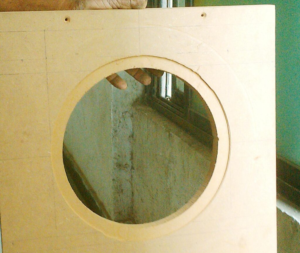
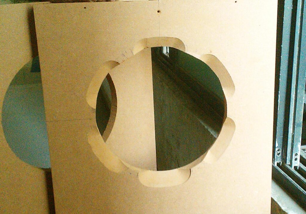
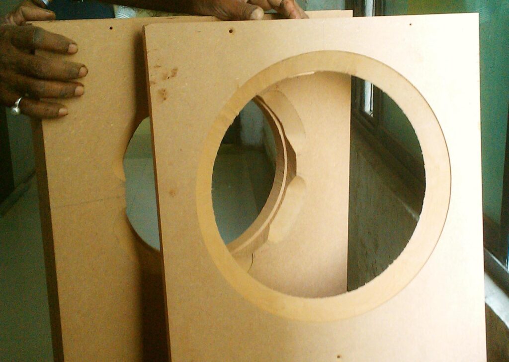
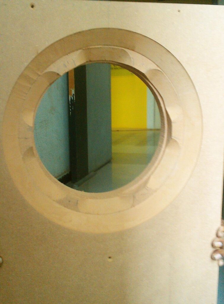
The chamfering trickery I used here allowed me to get a full two inches of MDF in which my wood screws would get place to grip, to mount the driver. I had not yet begun to use T-nuts, finding them to be more of a hassle than I needed. Six screws penetrating into two inches of MDF should be good enough to give me a lifelong grip on the 10″ woofer.
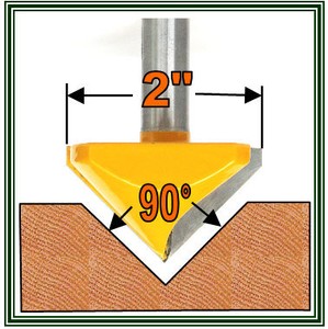
A special router bit
This chamfering of edges of the hole was done by a specific router bit:
This is sold on eBay US by the seller ghsu2ia3 who has been selling on eBay since 2000, and operates an eBay shop called Super Carbide Tools. He has a feedbackscore of more than 22,000 with 100% positive feedback. He’s clearly a serious businessman. His router bits ship from McHenry, Illinois, USA. I imported a bunch of bits from him through Borderlinx.
What’s special about this specific router bit? Well, it has these properties:
- It has no bearing at top or bottom
- it has a 45-degree slope and a 25mm depth (which means a 50mm top diameter)
Just try finding another router bit from somewhere else with these features. I couldn’t. This is special because:
- The absence of any bearing at top and bottom means that I can plunge this bit into thick MDF when it is rotating, and I can start my routing without drilling any leader holes. All other chamfering bits I find have a bearing at the bottom, which means they can cut from their sides all right, but they cannot cut downwards.
- The combination of 25mm depth and 45-degree slope angle is pretty rare. Even if I were to accept bearings, I found just one bit with 25mm depth and 45-degree slope, and it was selling for USD 57. The 25mm depth allows me to do chamfer cuts in 25mm-thick MDF sheets (and thinner sheets if I need to someday).
Therefore, I realised that this bit was quite special, and I would need it for all midrange and woofer mounting holes in all speakers I built in future. I have located and procured a Chinese brand router which can accept 1/2″-shank router bits, so these bits work very well for me.
And I am using the same trick of recessing which I have used in the past — the 4mm of veneer becomes one of the components to help me get the recessed fit of my drivers. If a driver (some tweeters) has a front plate thinner than 4mm, then I use a gasket behind its front plate to raise it and also give me the air-tight seal I need. This is how the Asawari tweeters were mounted, for instance.
Bracing, bracing… yet again
After I had gotten the woofer enclosure bracing framework and posted pictures to some online fora, some friends congratulated me, and one friend actually used the word “over-built”, all in a very appreciative tone. My chest swelled and there was a clear swagger in my step.
After the bracing was fitted inside the enclosure with Araldite and a few screws, I tested the walls with the good old knuckle test and lost all my swagger. The bracing was not helping as much as I had hoped. It was quite unbelievable — I had never built such a carefully designed bracing before, and I was still getting hollow sounds from the knuckle knocks.
After some thought, I realised that the side walls were not sticking to the bracing as tightly as I had wanted them to. Just Araldite on the edges of the bracing to fix it to the side walls is not of any use — one must press the pieces together hard while the Araldite solidifies. I had not done that. In fact, I had wanted to do that but my know-it-all carpenter had ignored it. I had asked him to drill holes every six inches or so, on the side walls and put screws through them to grip the bracing tightly after he fitted the bracing and before the Araldite had time to solidify. This would have meant at least about 25 screws on each sidewall. Instead, my carpenter had fixed half a dozen screws, pretty close to the edges of the sidewalls, just to hold the bracing in place. Now there was no way to remove the bracing and re-do it — the Araldite locked the bracing in place, making removal impossible.
I then made him drill holes every six inches as I had wanted initially, fill the holes with Araldite paste and then put screws through them and tighten. He thought it was rubbish and total overkill, but I can be as obstinate as he when the need arises. This was a hunch — I felt that the only way to make the side walls really stick to the bracing was to do this post facto hack. These holes had to be drilled from the outside precisely along the lines where the edge of the plywood sheets of the bracing lay on the inner surface. The carpenter carefully did it. He poured Araldite, tightened the screws.
And … it worked! After a day of the Araldite drying, I tried the knuckle test again and the side walls gave a satisfying “tup-tup” sound instead of the earlier “bonk bonk” hollow sound. I had managed to save my investment and deaden the sidewalls and work around my obstinate carpenter after all. That was one of the happiest days of my Darbari building story.
To those friends who had thought I was over-building, I say… “Think again!” рџ™‚
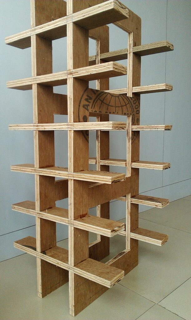
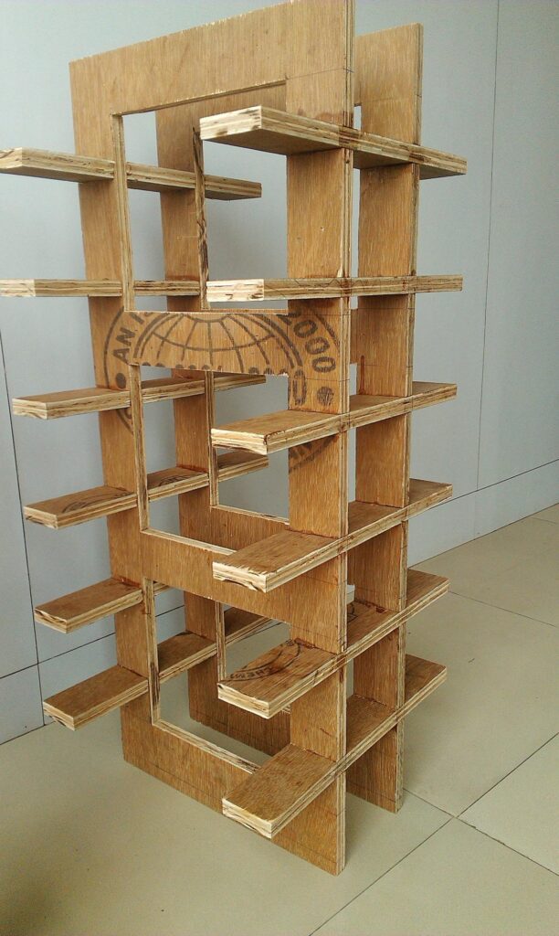
The upper enclosure
The upper enclosure was easier to build well, simply because it had smaller panels, therefore they turned out acoustically dead without much struggle. I used bracing similar to what I had used for the woofer enclosure, with slightly better results.
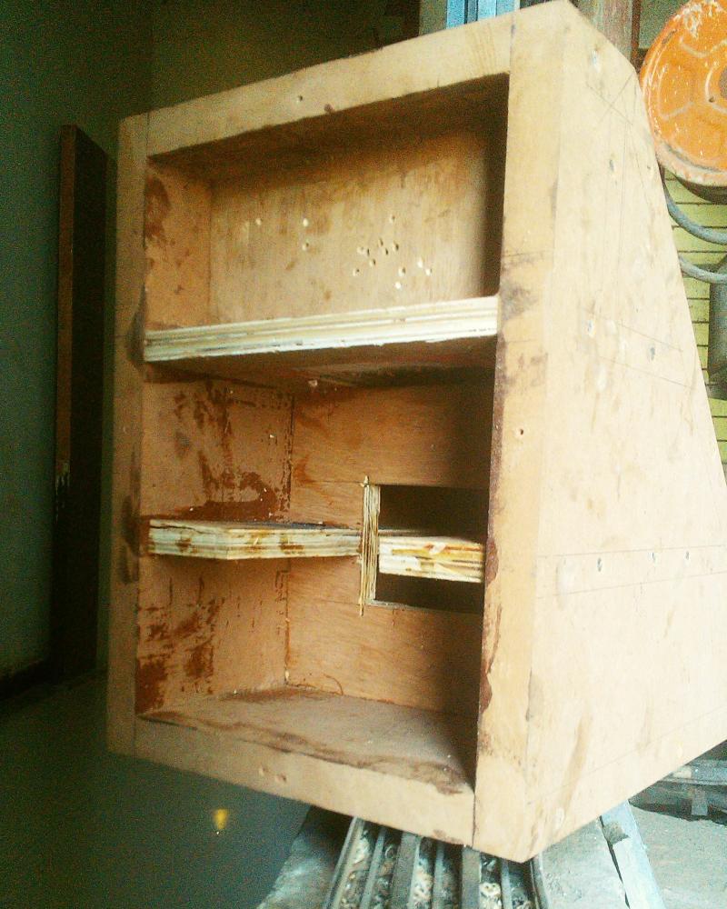
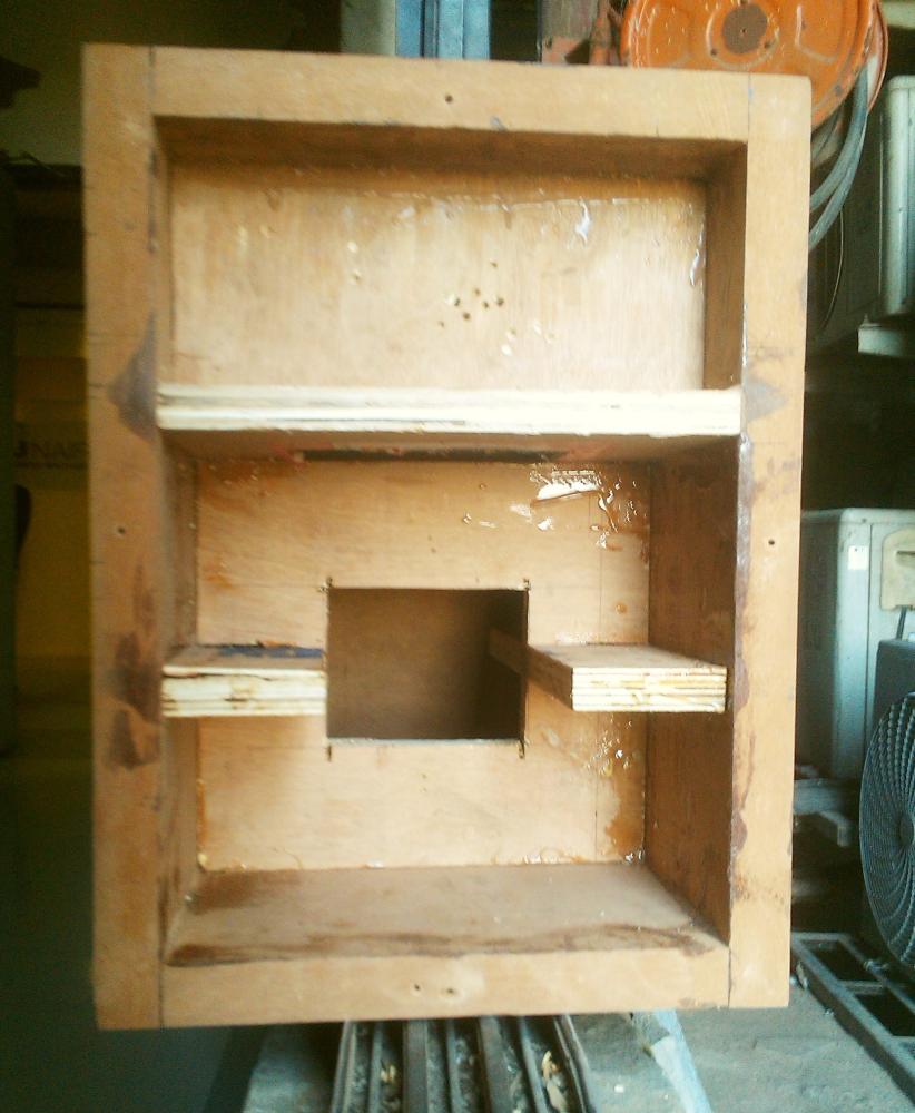
In these photos, a vertical brace is visible with a squarish hole in its centre. This would eventually be directly behind the midrange driver. On hindsight, this is probably going to cause unwanted levels of reflection of the back wave of the midrange driver, though it is doing its job as bracing of the side walls splendidly.
One point very visible in the photos is the tweeter chamber. It is a separate sealed chamber running the full width of the top of the enclosure. Such a large tweeter chamber is not required, but I built it that way because it’s easier to build than having a half-width chamber. But a sealed chamber is useful; it reduces vibration of the tweeter due to the back wave of the midrange driver. In the case of the Darbari, this issue may not be as serious as in the case of 2-way designs, because the deep bass which causes the hardest-to-manage vibrations would not be present in this chamber in the case of the Darbari.
After the front baffle was shaped and fitted to the upper enclosure, and the veneer sheet was glued on, this is what it looked like:
These photos clearly show the bevelled corners and the overall shape. The chopped-off corners and bevelled edges “soften” the boxy shape. One thing not very clear from these photos is that the front veneer is a much darker pattern than the ones on the rest of the surfaces (including the bevelled edges and corners). As a result, the visual impression of the boxes head-on will be communicated by the shape of the front pieces, which have chopped-off corners and therefore look a bit “rounded” if one may use the word.
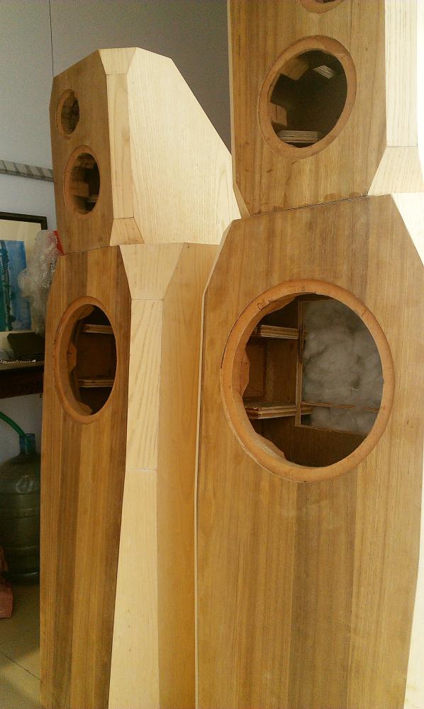
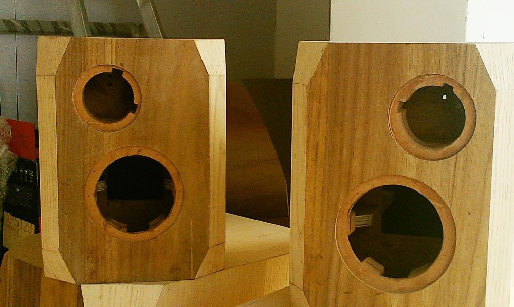
Enclosures are built
These are shots before the polishing, but after the enclosures are completely built.
Drivers are fitted
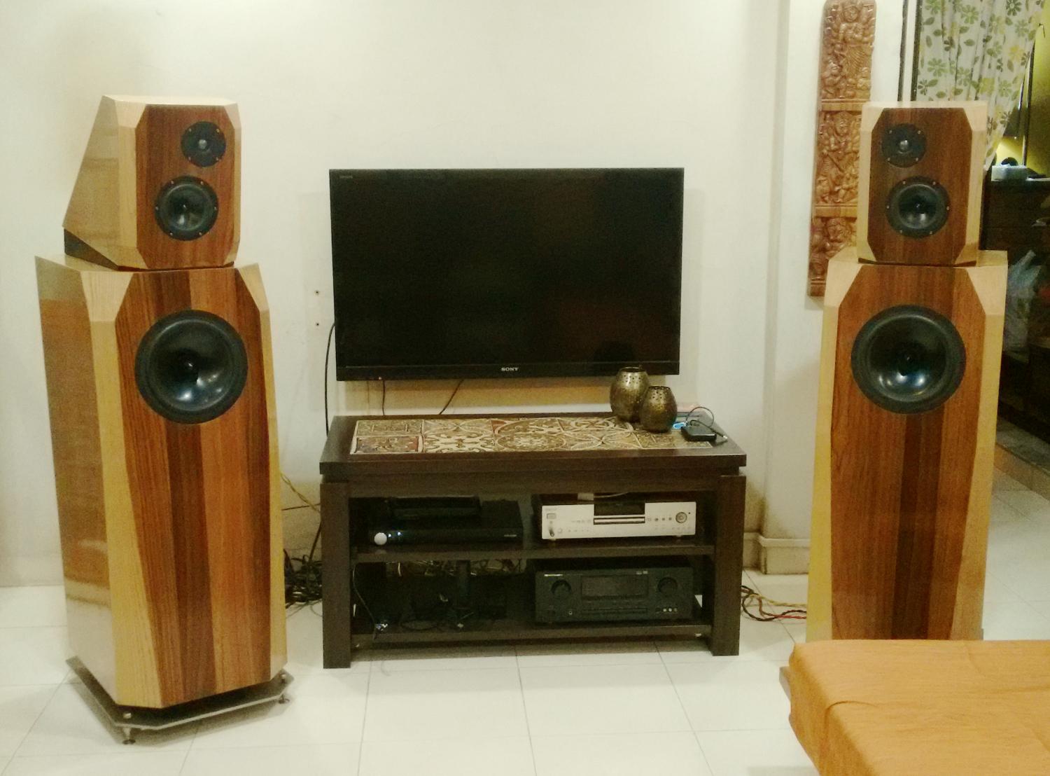
The glossy PU polish on the enclosures was done. Speakers were shifted to the living room. Drivers were fitted.
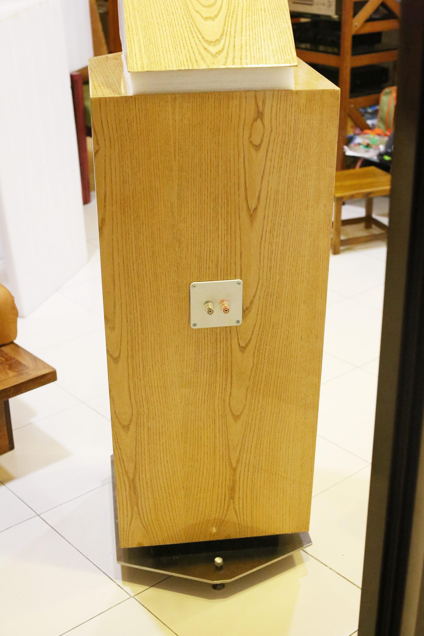
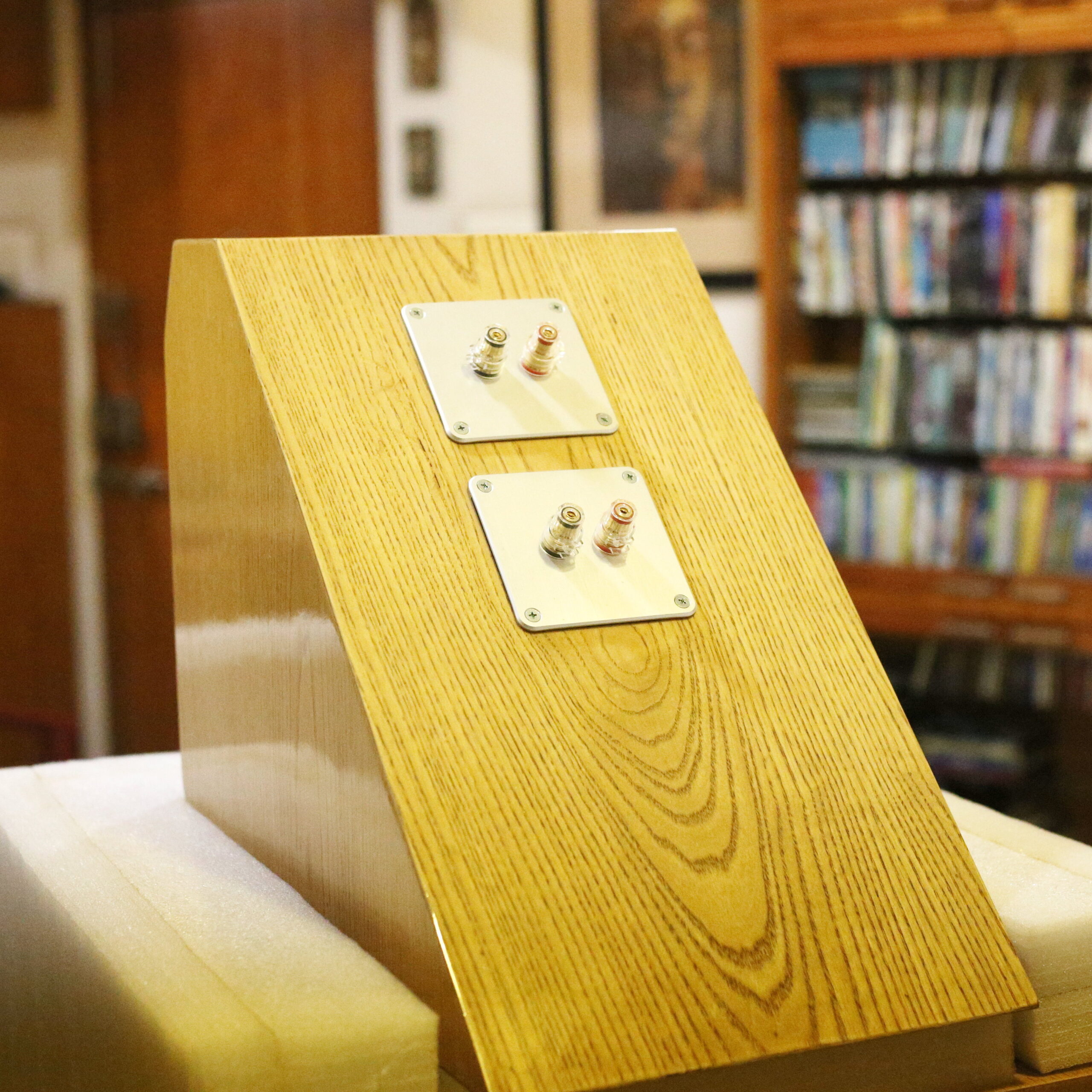
I used Dayton Audio insulated binding posts mounted on matching mounting plates also from Dayton Audio. Both items are very well made, and are easy to assemble and join wire leads to. I used female crimp-type QC interconnects to connect leads to the binding posts from the inside. I never depend on pure QC for a long-term connection, specially since the pollution in the Indian air makes surfaces acquire oxide and sulphate layers. So, I did soldering here too, but soldering QC to QC is a much faster and neater job than soldering bare wire to a binding post.
The speaker drivers were mounted using absolutely stunning hex-head screws from The Audio Crafts, a Delhi-based supplier. I have no idea where else these screws are available from. The screws I used were these copper-finish ones for the tweeter and midrange, and these larger black ones for the woofer. I would have loved it if TheAudioCrafts carried large ones in copper finish, but he didn’t. I also felt that 45mm was a better length for larger woofers, but he stops at 30mm. Whatever it may be, but the copper-finish screws made my speakers look like a million dollars.
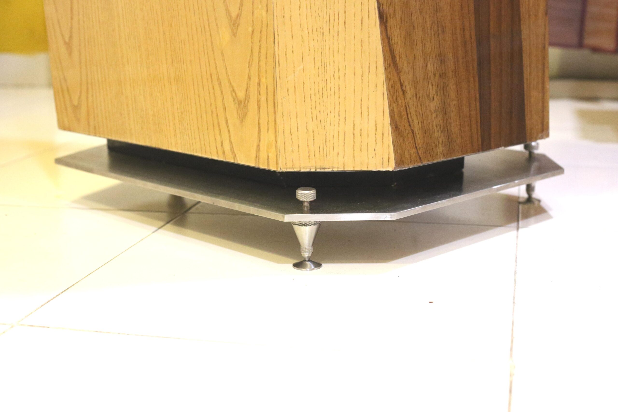
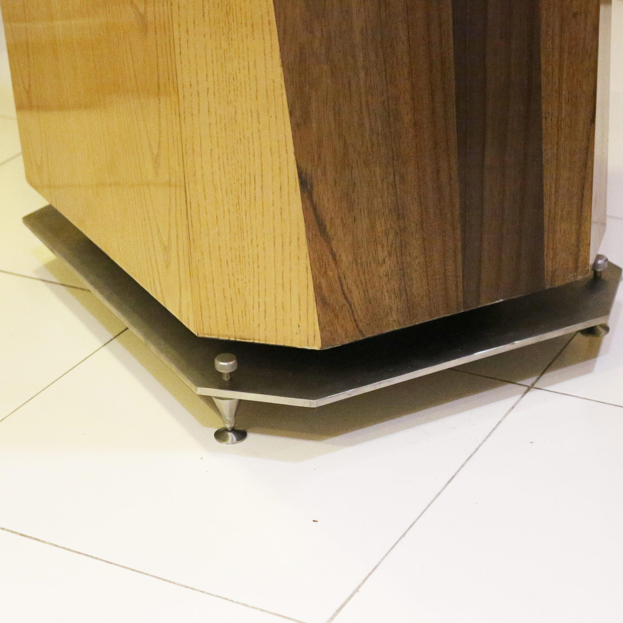
The speakers stood on three spikes and a metal plate. This metal plate was an 8mm-thick sheet of 304-grade stainless steel. It had been cut, drilled, tapped (for the spikes) and finished in brushed finish by Sound Foundations, an amazing boutique manufacturer of accessories for very high-end audio equipment. Ali of Sound Foundations does not make any money from his venture, I am quite certain. The spikes are manufactured by Sound Foundations, and he also supplies floor-saver discs for them. Each speaker stands on three spikes.
After listening to the speakers for a couple weeks, I decided to get some wooden wedges made to place between the upper and lower enclosures. This wedge tilts the upper enclosure forward so that the upper drivers point more directly towards the listener’s head, instead of firing above it. I placed a few dozen small vibration-absorbing pads on the bottom of each upper enclosure and on the bottom surface on each wedge. This absorbs vibration and also prevents slippage of the upper enclosure.
The speakers were a real dog to work upon, because of their size and weight. Fitting the metal plates to the bottom meant up-ending the enclosure, standing it on its head, placing the plate, drilling carefully, tightening four two-inch-long steel screws, then fitting the spikes, and finally, gingerly, carefully, laying the box on its side and straightening it up. Each steel plate weighs 14kg. I suspect each channel’s speakers (upper and lower combined) exceeded 100kg.
Measurements
My usual measurement rig was put to use.
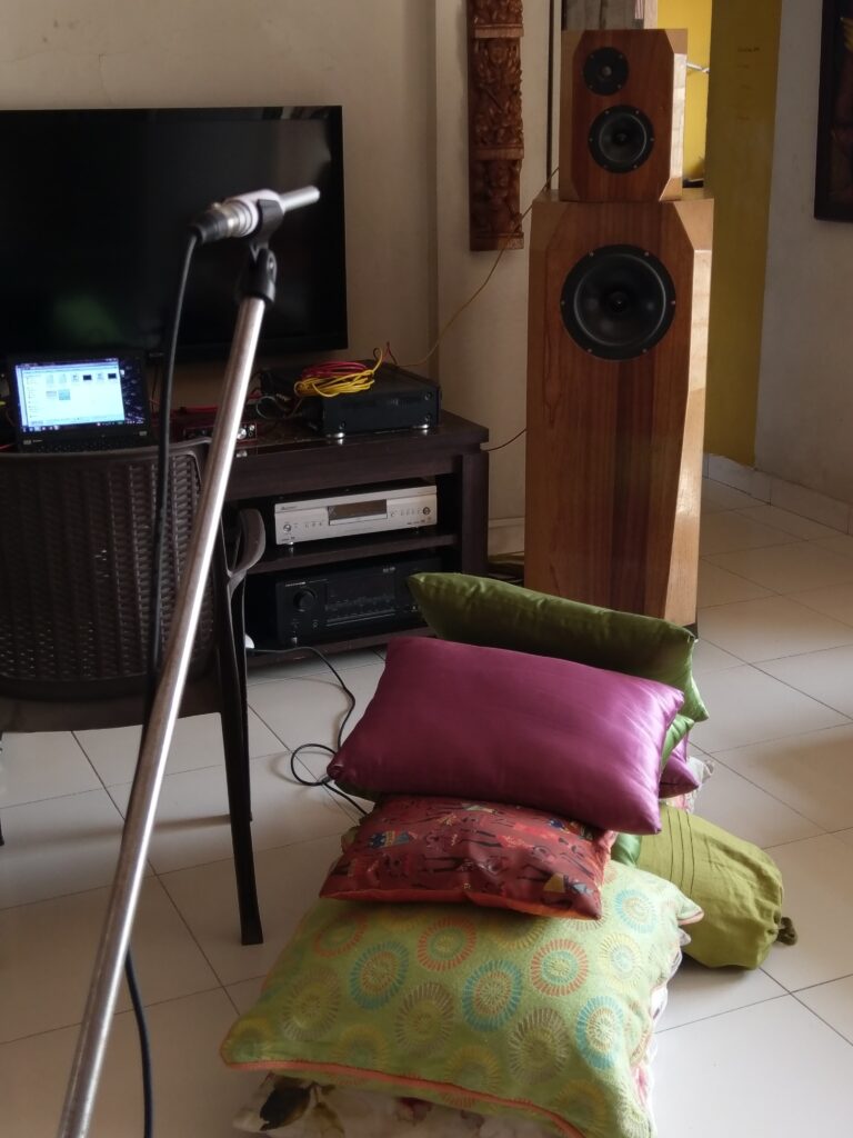
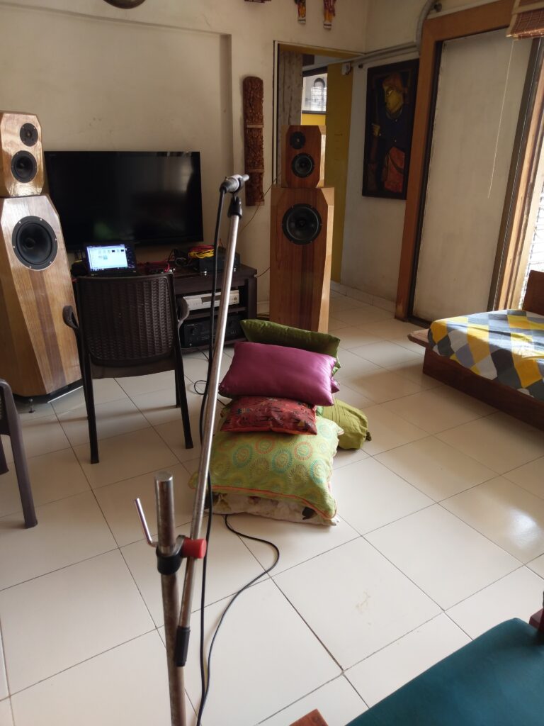
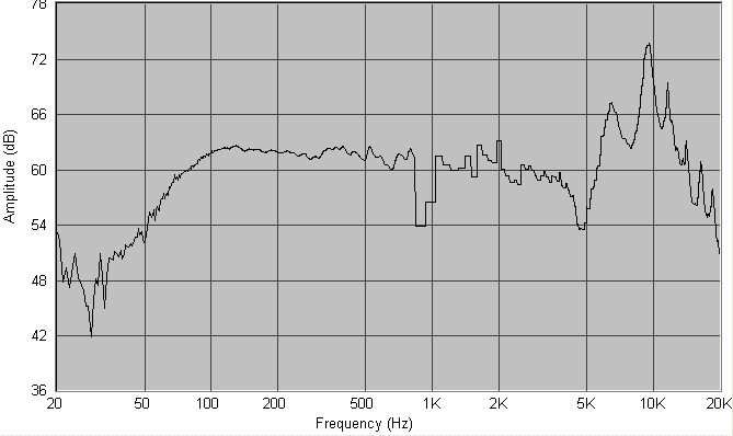
The pile of pillows on the floor proved quite ineffective in suppressing floor bounce. Not that it obstructed my gated farfield measurements.
The midrange and tweeter measurements
This pair needed to be measured carefully to build an accurate crossover. Not only did we need to address the cone breakup challenges of the midrange, we also needed to have a carefully phase-coherent crossover point between these two drivers. Set up my Dayton mic and Speaker Workshop and took some measurements. This is what I got.
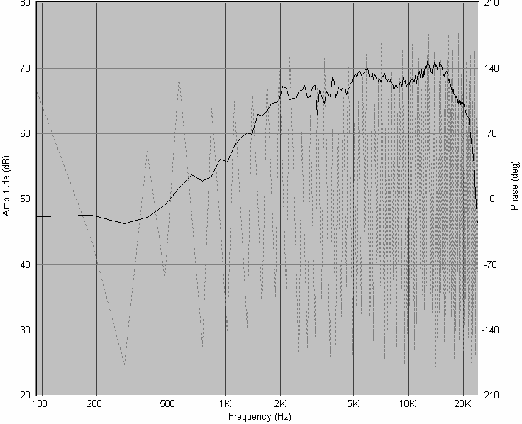
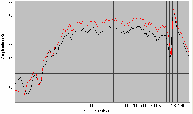
Here is the published and the measured SPL curve for the tweeter. The published curve is screen-grabbed from the Scanspeak Discovery datasheet.
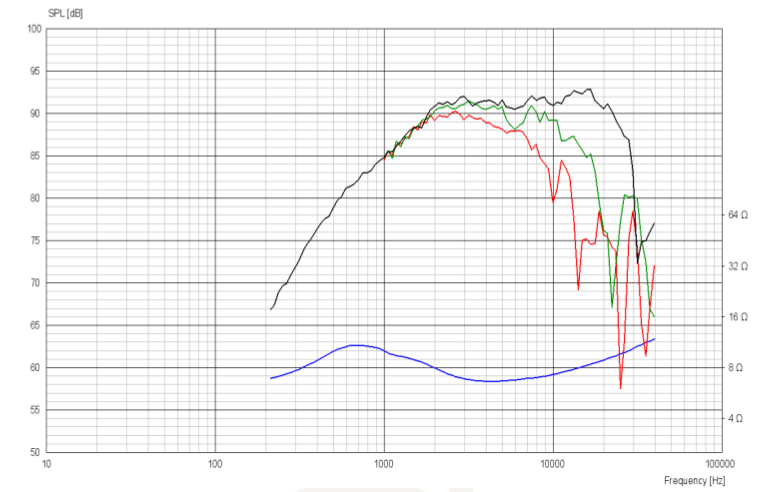
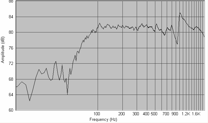
And here is the published and the measured SPL for the midrange (the Dayton RS150).
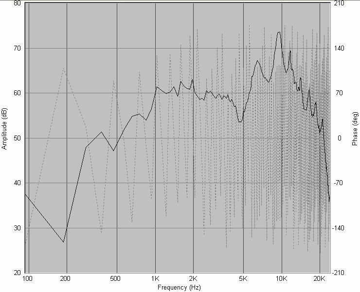
It was nice to see the measured responses similar to the published curves. Some of the differences between them would be due to my measurements being on the actual enclosure while the published figures are of drivers fitted on an IEC baffle.
Both these measurements were taken with the mic in the exact same position and with the various gain settings unchanged, therefore I was certain that I was getting accurate relative amplitude and the data was phase-aligned for crossover design purposes. No time alignment to correct here.
Nearfield measurements of midrange and woofer
The woofer measurement needed to be near-field. I didn’t need to worry much about its phase coherence (at frequencies as low as 150Hz, phase is a pretty gross issue) and its amplitude would be corrected by parametric equalisers in my crossover anyway, for room correction purposes.
I put the mic a few millimetres from the cone of the driver, adjusted gains at various points, set the number of repetitions in Speaker Workshop measurement settings to 20, and fired away. I realised how sensitive the gain settings were for nearfield. A tiny turn on the mixer’s gain knob made the VU meter reading in SW jump from 18000 to max. Got to tweak it to keep it somewhere in the 20,000s.
I took three pulse readings of each driver, moving the mic around a bit, keeping the mic a few mm away from the cone, and somewhere off-centre. I then took a fourth reading placing the mic exactly a few mm in front of the tip of the phase plug. The textbooks say that nearfield measurements need to be taken with the mic in front of the dust cap, but then the dust cap moves with the cone, but these drivers have phase plugs, and phase plugs don’t move. Therefore, I thought I’d take a few readings from just in front of the cone surface and one from in front of the phase plug.
While taking the woofer readings, I got lazy and did not move the mic around much for the first three. The fourth, with the mic in front of the phase plug, was done by moving the mic to the new position.
From the pulse measurements, I computed the frequency response curves, ignoring gating and taking into account the mic’s calibration curve. I used the Blackman algorithm for the transformation. (Does the algorithm make a big difference?)
This is what I got for the midrange.
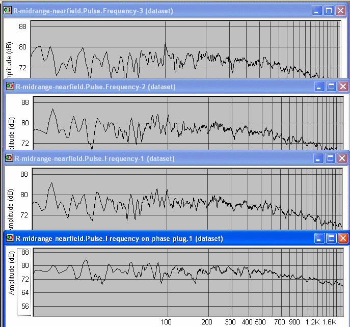
And this is what I got for the woofer.
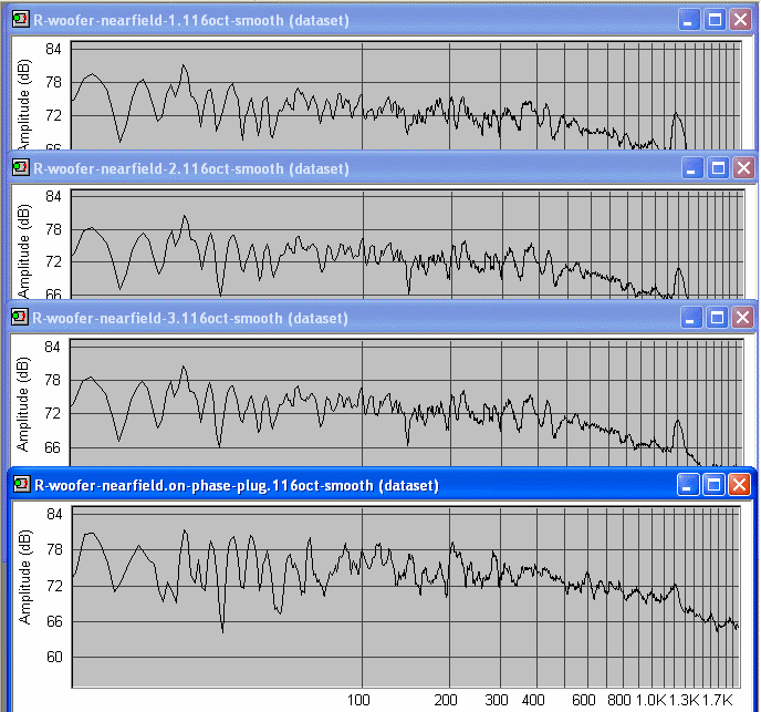
All the curves have X-axis from 10 Hz to 2000 Hz. All curves have been smoothed to 1/16-octave. The raw unsmoothed curves were very “hairy”. I don’t usually smooth my measurements, but these were uniformly too hairy to look at. My gated farfield measurements have no smoothing.
I have shown all four readings in each case. There are repeatable peak-to-peak spikes and troughs of 10-12dB in both drivers. What causes these?
Try as I might, I could not get clean and realistic-looking graphs. I tried with both the midrange and woofer, at various mic distances, various sampling rates and sample sizes, at various gain settings. Nothing worked. So I called up Gooroo Angshoo, who was my go-to gooroo when all else fails. He suggested various things, but one of his suggestions struck me: he said that he never takes a pulse response for nearfield measurements. He takes a direct nearfield frequency measurement by telling Speaker Workshop to do the job. (Internally, the software must be going by the pulse route, but somewhere there is a difference.) So I tried it and immediately got believable curves:
For the midrange, I got this:
From these graphs, it was clear that I was getting acoustic rolloff of the mid at about 100 Hz, and for the woofer at about 50 Hz. I did not need the precise Q of the rolloff, because the final sound I would experience would be impacted much more by room modes than the Q of the speaker.
So, now I proceeded to crossover design.
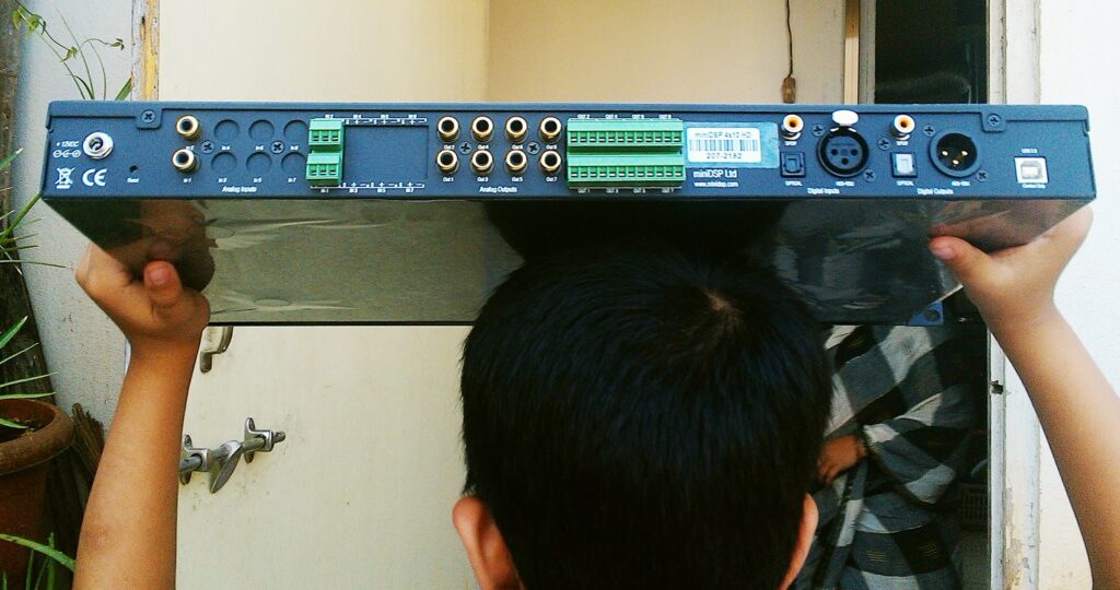
Crossover design
The MiniDSP 4x10HD was the core of my digital active crossover. Here are front and rear views. Today, one would probably use one of the MiniDSP Flex series of products.
Crossover for mid-tweet
I loaded the measured data into the ACD (Active Crossover Designer) spreadsheets. I completely skipped any attempt to get my SPL data to be minimum-phase, and I also skipped the ACD step of using a summed-SPL measurement and then playing with individual driver delays to find the acoustic centre distances or offsets. I already had phase-aligned SPL measurements of tweeter and midrange from the measurement exercise described above, so I didn’t need those things.
I started tweaking with filters. Progress was meandering, with a lot of back-and-forth movement and experimentation. I will try to illustrate the steps in a more systematic narrative, to explain the crossover, not the actual experimentation process.
The initial state of the SPL curves
This is what the SPL curves looked like in ACD when I loaded the raw FRD files into the spreadsheets:
At this point, things look scary and impossible to tame.
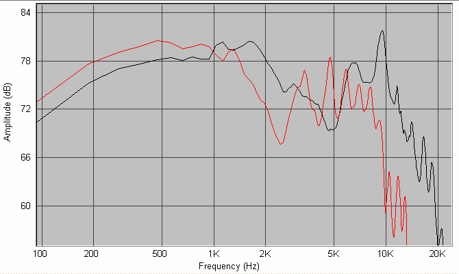
Step 1: tame the midrange cone breakup
I applied two notch filters to cut down the midrange driver’s cone breakup and push them down as much as I could. I did a wide 20dB cut, Q=0.3, at 10KHz and another narrower 10dB cut, Q=0.7, at 7KHz to arrive at this picture.
Step 2: the low-pass for the midrange
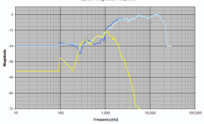
Next I applied two cascaded second-order filters to get the low-pass filter on the midrange. The final figure of Q and frequency were not arrived at by magic — they were the result of a lot of tweaking which happened later. But for the purposes of a structured narrative, let us assume that I got some magical inspiration and applied the final values for the low-pass stages. This is what I now saw. The cone breakup region had been pushed out of sight, and I was very happy to see them go.
I was only interested in the region of 1KHz to 2KHz in the midrange curve here. Below 1KHz, my gated farfield measurements were showing me some invalid zigzag jagged curves — I would need nearfield data to get that part right. And above 2KHz, the tweeter would take over, so I didn’t care about the midrange. I intended to cross over to the tweeter at about 1.5KHz, so all I cared about was the midrange curve between 1KHz and 2KHz right now.
Step 3: bring the tweeter level down
The tweeter was much more sensitive than the midrange and this showed in the relative levels of the two drivers. I put a gain stage with a gain of -7dB to bring down the tweeter level.
Step 4: high-pass filter on tweeter
Then I applied a high-pass filter, 2nd order electrical, on the tweeter. Given the already prominent acoustic rolloff of the tweeter, I figure that a second-order electrical filter would be adequate.
All of a sudden, the summed SPL curve (dark blue line) between midrange and tweeter began showing a promising flatness. The critical region between 1KHz and 2KHz looked promising. My spirits rose.
Step 5: shelving filter on tweeter
I now wanted to tame the rise in the tweeter’s SPL curve beyond 4KHz. I tried a first-order shelving filter from 5KHz to 10KHz, and this is what I got. The top-end was tamed all right, and things look very polite and disciplined.
Step 6: shelving filter tuning
By studying the curves, I figured that the shelving filter was making things a bit too tame. A bit of rise in the tweeter between 10KHz and 20KHz is not a totally bad thing, specially if I would be listening somewhat off-axis most of the time. This region could take a bit of rise, and would add a bit of “air” to the sound, a touch more detail, without adding any harshness or changing the tonal balance of the sound. So, I decided to tone down the shelving filter a bit, allowing the SPL to rise a bit. I changed the range from 5KHz-10KHz to 5KHz-7KHz. And this is what I got.
Step 7: the tweeter peak at 6KHz
What remained now was the tweeter’s peak at 6KHz. This would be audible, and I would rather tame it a bit. I played around with the parametric equaliser, and put a notch centred at 6KHz. I play with the amount of cut (between -1dB and -2dB seems good) and the Q (I tried values of 0.5, 1, etc). I finally settled for something like -2dB and Q=1.0.
The reverse notch
After this, I flipped the polarity of one driver, to see if I was getting a good, deep notch. A notch tells you that the summing of the two drivers on the mic axis is working well, and the power output is not “lobing” upwards or downwards”. Slight differences in phase of the two drivers will drive the power output vertically up or down, away from the mic axis (i.e. away from the listener’s head). This causes subtle complications.
But I did not get a deep notch. Evidently, the mixture of filters I had applied had driven the drivers into a subtly out-of-phase state at the crossover point.
So I played with adding delay to the midrange. I tweaked all sorts of values, keeping an eye on the reverse-null depth. I finally landed up getting a decent null if I chose to reverse the polarity of one of the drivers, and adding a small delay (a quarter millisecond) to the midrange.
Here is the summed SPL. One driver is wired with reverse polarity to get this total response.
When both the drivers are connected with the same polarity, then this is the anti-phase null I was getting:
It is more difficult to model a crossover using ACD than with “normal” speaker modelling products (Speaker Workshop, LspCAD, SoundEasy) because there is no goal setting and auto-optimisation available here. You have to tweak each value by hand endlessly and keep looking at the SPL curve. But the whole setup works, and for the price (free!), this is the only crossover design and modelling tool I knew of which allows you to model active line-level analog crossovers. This was before VituixCAD.
Getting the driver phase right with minimum offset
I played around with the time delay and tried to see if I could arrive at the anti-phase null without flipping the polarity of one of the drivers. I finally managed to do it, delaying the tweeter by 0.06 msec instead of the midrange, and keeping the drivers with identical polarity. I felt much happier with this, because the time delay was much smaller than the earlier case (about one-fourth) and the drivers were in same polarity. I am not showing any new SPL curves, because they look almost identical to the earlier ones.
The woofer-mid crossover
I needed to tackle this beast, and I need to verify the acoustic rolloff of each of these drivers in its own sealed chamber. My nearfleld measurements gave me that picture. Now for the crossover.
I was clear that I wanted to do a simple fourth-order or sharper crossover, and leave it at that. I do not feel that it matters whether the resultant acoustic rolloff at these low frequencies is 24dB/oct or 32dB/oct or something else.
But I knew I would have to take these SPL curves into ACD and get MiniDSP biquads for at least the midrange driver, because the MiniDSP configuration application allows you to either work with raw biquads or in the “Basic” mode with simple crossover specifications. My upper-end filter (the low-pass) for the midrange was complex and subtle enough for me to need biquads — the “Basic” mode would not do. So I would need biquads for the lower-end filter (the high-pass) too. Therefore, I thought — why not try to take the combined nearfield+farfield measurements into ACD and see what the filters looked like in the modelled SPL curves?
Splicing the midrange curves
Splicing the nearfield and farfield curves is not as easy as clicking “OK”. You have to manually match the levels of the two curves, and then experiment with the splicing frequency, before you can get something which looks good.
My farfield measurement of the midrange had sensible data from 1 KHz onwards. Below 1 KHz, it was rolling off in an unacceptable manner. I decided to splice the nearfield data at some point near the 1 KHz mark.
But my nearfield data had some unrealistic peaks which were (I am told) the result of measurement artifacts. Therefore, 1 KHz seemed to be a very unstable spot, since both graphs were showing problems at this point. So I made various attempts to get the SPL to match and splice at various frequencies from 840 Hz to 1 KHz, to see what I could get. Finally, this is what I got.
This one had a major crevasse in the 850Hz – 1KHz range, but I decided to ignore this completely. After all, I was doing all these things to get the mid-woofer crossover done. I did not need to look at the curve at 1 KHz while working on the mid-woofer crossover.
Adding the woofer into the picture
I now needed to load the woofer curve into ACD. This would be entirely the nearfield data; I could completely ignore the higher frequencies in this curve, knowing that they were probably invalid, because I only needed to design a crossover at 150 Hz.
So I loaded the woofer curve into ACD. But the absolute levels of the midrange and woofer curves were diverging hugely, due to all these inconsistent and independent measurements. (When you measure two drivers and move the mic in between, or change gain settings, then their relative SPL values cannot be understood from their SPL curves. This means two nearfield curves of two drivers can’t be compared for relative SPL.)
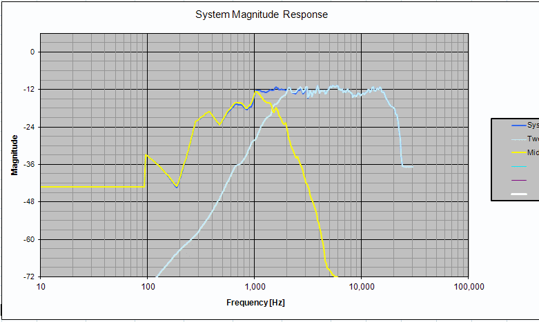
So I decided to do a cross-check of the relative SPL of the midrange and woofer curves, by taking one shot of gated farfield reading and keeping the mic and gain settings unchanged. This is what I got, shown here with midrange and woofer data superimposed:
I could see that their relative SPL was roughly similar. More accurate comparison was not needed at this stage, since we are discussing really low frequencies here, and room modes would play a huge part in what the listener actually hears. Those room modes would be tackled later by in-room measurements anyway, so I could safely ignore them here.
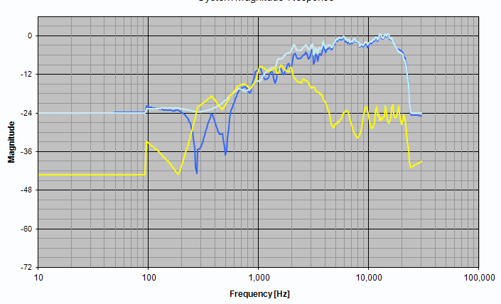
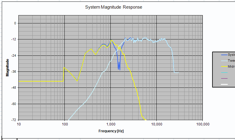
Now that I had the woofer and midrange data in ACD, level matched to roughly the same level, I could apply the high-pass filter on the midrange and the low-pass on the woofer, and see what it looked like. This is what it looked like:
Here, I was totally ignoring whatever the graph was showing me as interaction between the midrange and tweeter. The spliced midrange curve did not have the same phase alignment as the original pure-farfield midrange curve, therefore the crossover point between the mid and tweeter was showing jaggies. I ignored that. I paid attention to the woofer-midrange crossover.
The final acoustic rolloff of the mid’s high-pass is steeper than that of the woofer, because the natural acoustic rolloff of the mid were added to the 4th-order electrical filter. The woofer’s low-pass, on the other-hand is showing roughly an acoustic 4th-order rolloff, because there was no natural rolloff for the woofer in the 100Hz – 500Hz band.
Ah well. This is as precise as it gets as these low frequencies when building speakers in bedrooms and living rooms. The final in-room behaviour would be something else anyway. I had my crossover, so I plugged them into the MiniDSP and proceeded to build a prototype.
The combined, final picture
The tweeter filters and eq settings now look like this:
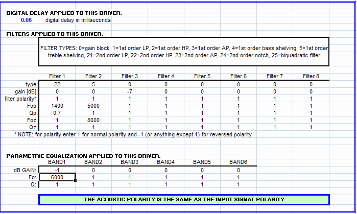
There’s nothing sacred about the shelving filter settings or the shallow notch — they could be tweaked to taste.
The midrange filters and eq settings look like this:
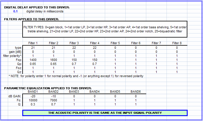
There was a strange 0.1 msec delay on the midrange. This was something I just put in, because it made the mid-to-tweeter crossover look a little cleaner, after I put in the spliced-nearfield-farfield midrange curve with the jaggies at 1 KHz.
The woofer filters looked like this:
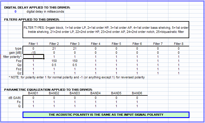
The -18dB gain cut is to be ignored — it has no real value. It was just put in there to gain-match the woofer visually with the midrange.
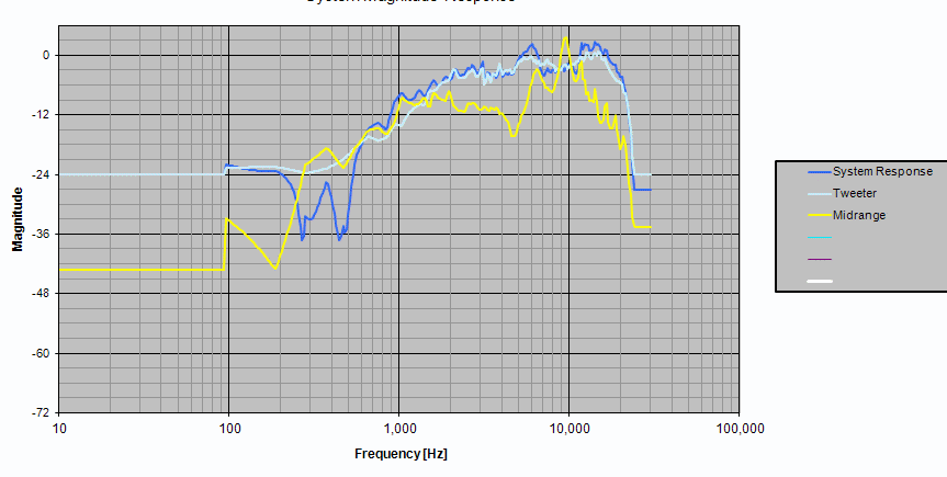
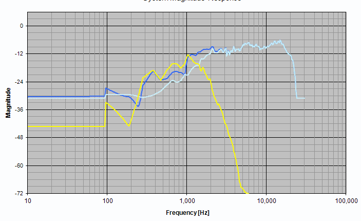
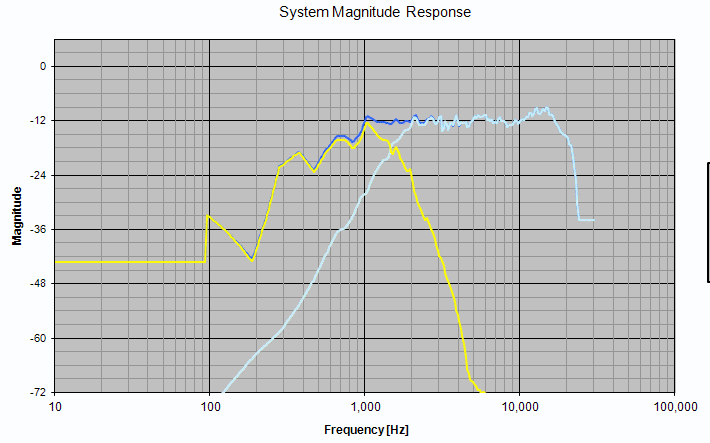
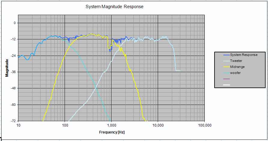
And when all this is put together, in a highly contrived modelling setup, this is what I got:
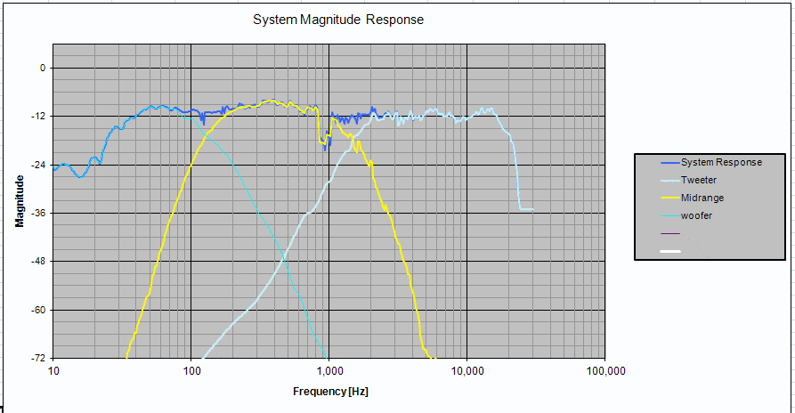
It all looked tolerable. Now for some real-world listening, followed by more measurements.
Baffle step compensation
A bit of listening showed up a very clean sound, with detail but without any harshness. However, one of the most obvious problems was the weak deep bass.
Some heart-burn and some thought later, it became apparent that I had missed one important component of the crossover design: the baffle step compensation. This is a subjective element one must add to the system response, increasing the lower frequencies by anything like 3 dB to 6 dB. Which frequency to start the shelving filter from? This is supposed to be decided by the baffle dimensions, but the Darbari has two dimensions for its baffle. The midrange, which goes pretty low for a midrange, had a baffle width less than a foot. And the woofer had a width considerably more than this.
So I decided to do a first-order shelving filter to raise the response below 300 Hz, up to 150 Hz. That’s about a 4-5 dB of rise. I also decided to cut the mid and tweeter response by 4 dB compared to the woofer. Overall, the modelled SPL curve now looked like this:
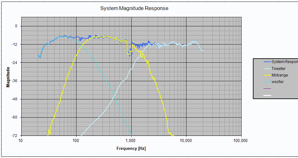
I listened to this for a few days.
Further enhancement of the lower octaves seemed to be hard to do. I tested the woofer by feeding it a sine wave of 50 Hz, and it seemed to bottom out at power levels between 100 W and 150 W. Therefore, it did not have the mechanical construction to handle a lot of low-frequency boost, and I was thinking that I would just let it roll off at its acoustic roll-off point. My box modelling seemed to indicate something like a Q of 0.6 or less, which means a gentle roll-off, giving a likelihood that it would fit in well with the room gain which the in-room responses would have.
Crossover tuning
Everybody knows that a 3-way crossover is much more difficult to design than a 2-way, and this was my first 3-way project. I was expecting difficulty, but the challenges I faced were interesting and unexpected. (And yes, in case you wanted to ask: after the v1 crossover, the Darbari did not sound as good as my good 2-way designs had done.)
Problems
I could see three problems, some quite unexpected:
- Reverb: this was audible with male voices in music, but much more audible in movie soundtracks. I am very familiar with these movies, and when there were actors speaking in quiet environments (no echo or reverb in the venue), I could now hear a reverb. This was actually making it difficult to catch the words sometimes.
- A nasal twang: this was audible in a lot of music. There was a high-frequency distortion of some kind, making voices harder and well, weirder.
- Recessed midrange: this seemed to be the simplest to attack, given that I have an active line-level crossover with lots of parametric eq channels, but I was not sure. Maybe it was not as simple as it seemed.
- Soundstage: in a word, not as clean as I have experienced from my 2-way MTM Asawaris. Specially true of lower frequencies like male voices.
Attacking the nasal twang
A friend came over for a listen, and said “It seems as if the bass sound is overlapping with the tweeter, with the midrange in between the two.” Taken literally, this makes no sense, but I began to wonder: was the nasal twang due to the woofer extending too far into the high frequencies?
I sat down with the console of the MiniDSP plug-in, and muted one entire side (three output channels in my case) and the tweeter of the other side. What I was left with was just the midrange and woofer of one side. I kept playing some movie soundtracks there, where it had male voices indoors with quiet background noise. The reverb and the muffling of the voices was quite perceptible.
I had put a 4th order electrical low-pass on the woofer, at 150 Hz, therefore giving relatively little chance for it to extend into the regions where it could add high-frequency colouration. But the woofer had seriously massive cone breakup from about 2 KHz onwards, therefore making it possible that even a 4th order electrical low-pass four octaves away was not enough.
So I went click-click on the GUI of MiniDSP and changed the low-pass from 4th order to 8th order.
Immediately, the male voices cleared up and the nasal twang disappeared.
So much for 4th order crossovers. One either needs notches to tame the cone break-up, or a steeper slope.
What was both interesting and disconcerting was that the reverb effect reduced a lot too.
Hunting on the time axis
I then decided that the reverb was due to misalignment in time between the woofer and midrange. With a shallower slope, there was a wider band of overlap, therefore the reverb was quite prominent. When the woofer low-pass slope became twice as steep, the reverb reduced, not because the time alignment improved but because there were much fewer frequencies which were being emitted by both drivers.
So, I decided that the right way to address this would be by experimenting with the time alignment. Not having any mechanism to check time alignment using conventional SPL measurements (MLS doesn’t work at 150 Hz in an average living room) I decided to do it by ear. And after a lot of trial and error (delaying the woofer, delaying the midrange, and everything in between), I got a hang of things — a bit. I kept playing clean voice passages from movie soundtracks, and kept listening for the reverberating-room effect. After some pretty frustrating back-and-forth, I felt that delaying the midrange by 2 msec seemed to be getting a clearly cleaner sound than before.
I stuck to that. And I wish I knew how to get it more accurately aligned. I “hunted around” on either side of the 2 msec mark, but without any perceptible improvement.
The soundstage improved too. It seemed to be “behind” the plane of the speakers, but it was cleaner than before. Placement of sound sources was more accurate.
Crossover v2.0
Having agonised over my travails for some time, and having received some feedback and pointers from John Reekie on the MiniDSP forums I decided to bite the bullet and re-do the crossover completely from scratch.
So, this is what I now did.
The mid-tweeter crossover
I first set up the midrange and tweeter to cross over correctly. I decided to make the midrange low-pass slope steeper, to ensure that the cone breakup was suppressed even more than before. So, I did an LR4 at 1500 Hz, and a second LR4 at 3000 Hz. Thus, in the region of the cone breakup, the slope would be 48 dB/octave. I learned this by observing the Cauer eliptic filters in Jon Marsh’ Natalie P design on htguide.com.
This is what the midrange filters looked like:
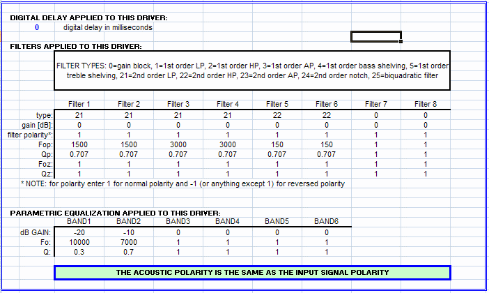
I increased the slope of the tweeter high-pass to 4th order electrical this time, to ensure that there would be no load on the tweeter due to low frequencies pushing the coil too far. The earlier 2nd order electrical was giving me roughly 4th order acoustic slopes, but this is safer. So I applied a simple LR4 on the tweeter, at 1500 Hz.
Then I played with the delay on the tweeter to get the two to time align and give me a deep reverse-null notch. I found that a delay of 0.37 msec worked well
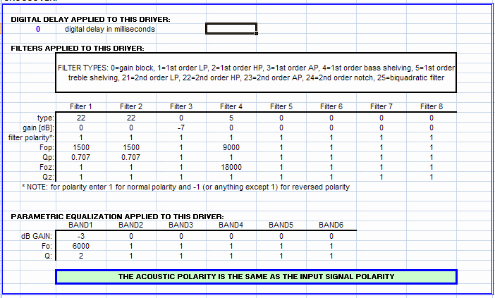
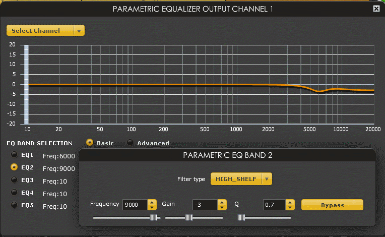
I did not transfer biquads for anything from ACD to the MiniDSP console. I went to the GUI of the MiniDSP console, entered the high-pass details (a simple LR4) and dialed in the EQ needed for the tweeter. This included one notch at 6000 Hz and a shelving filter to suppress the frequencies above 9000 Hz a bit.
I did not put any high-pass on the midrange. I left it to roll off as per its acoustic behaviour (about 90-100 Hz, with a shallow Q). I selectively picked up the biquads of the low-pass from the ACD and entered them into the MiniDSP console.
And I played some music. So, this was temporarily a TM 2-way speaker with a sealed chamber, crossed over at 1500 Hz.
It sounded lovely. The low bass was distorting a bit, but wherever there was no real low bass, it sounded lovely. Just the way speakers should. I tore myself away from my communion with BB King and went to the next stage.
Adding the woofer
I decided to simply apply electrical LR4 on the woofer (low-pass) and the midrange (high-pass) and leave it at that. So, at this point, I carefully inserted two more biquads for the midrange crossover, for its high-pass, and used the basic-mode GUI to set an LR4 low-pass for the woofer. The crossover frequency is 150 Hz.
To do some token phase matching, I dialed in a further delay of 0.3 msec, out of thin air. This means that the midrange is delayed by about four inches to compensate for the relatively deeper shape of the woofer, and the tweeter is delayed a further 0.37 msec (equivalent to another four inches) to make it phase-align with the midrange. So the total delay on the tweeter was now 0.67 msec.
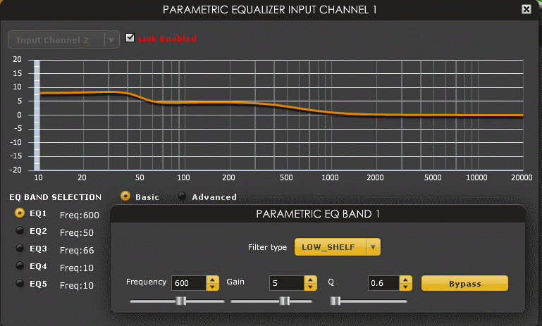
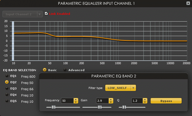
I went to the input PEQ panel of the MiniDSP console and dialed in a shelving filter to boost the bass below 600 Hz by a few dB, to do baffle step compensation. I also added a second shelving filter to boost the range below 50 Hz by an additional couple dB, to push the woofer’s roll-off from its natural 50 Hz to something a bit lower. I did not do any accurate modelling — I just dialled these in to see how they sound.
Then I played music. It sounded good. I played with the PEQ a bit more, changed the amount of baffle step compensation and its shelving frequency a bit, etc, and finally left it at a certain point and just sat back and listened.
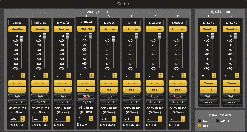
The MiniDSP console settings are shown below. At the input stage, I set the following two PEQ filters, for baffle step compensation and a bit of low-bass extension.
At the output stage, I set various things for various drivers. The first thing to do is to set the relative delays of the drivers, and set the tweeter level down by 7 dB to compensate for its higher sensitivity.
Then come the various crossovers and PEQ settings of the different drivers. First, the midrange crossover. Nothing to make sense of here, because it’s all done by biquads.
Then the PEQ settings of the midrange. We have two, for two notches. Both are done using biquads, because the GUI controls in basic mode do not allow notch depth greater than 16 dB, and we want 20 dB at one point.
Now comes the tweeter crossover. No biquads needed here, because basic mode is good enough to set a simple LR4.
Then there are two PEQ settings, one a notch, and the second a shelving filter.
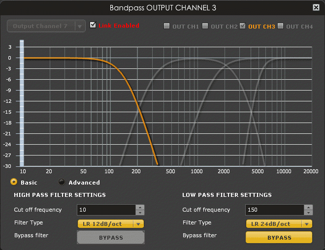
That takes care of the tweeter. Now for the woofer. Once again, it’s a simple LR4 low-pass done in basic mode.
This concludes the story of the crossover v2.
The earlier problems and observations
If the crossover v2 delivers very good results, why did the earlier attempt give so much problems? Where did the reverb come from? I could not even reproduce the reverb-like sound by rolling back the settings to earlier settings. Where did the nasal twang come from?
I have a few thoughts:
- The nasal twang was probably due to one, or both, of two things: the hump in the tweeter’s SPL curve around 6000 Hz, and the not-very-steep attenuation of the cone breakup of the midrange. In the crossover v2, I added a notch to completely flatten the tweeter’s hump at 6000 Hz and added a second low-pass 4th order on the midrange at 3000 Hz to further suppress the cone breakup.
- The reverb effect was, I am sorry to say, most probably due to some transient problem in the MiniDSP. I have observed strange control problems with the MiniDSP, and on one occasion, I have actually seen it in an undocumented state.
The MiniDSP instability which I have seen is quite interesting. In my case, it seemed to happen because the MiniDSP console lost control over the appliance, because my laptop went to suspended state during idle periods and then woke up again. On wake-up, everything seemed okay on the surface, but attempts to control the appliance by changing settings from the GUI would sometimes work, sometimes not. On one instance, I found that the appliance was not responding at all to any changes in settings.
On one occasion, I discovered that the appliance had gone into a peculiar state where the fourth input selection LED was on. I use the TOSLINK digital input, which is the second LED. I was baffled how it had switched to the fourth. I tried clicking the control knob on the front panel and rotating it to select the second input back again. I discovered that as I turned the knob, the other LEDs would switch on and off, but the fourth LED remained lit. It was clear that the appliance was in an indeterminate state. I power-cycled the appliance and everything came back to a normal stable state.
I would suggest that other users of MiniDSP be careful of such instability. Make sure your console program is healthy, and it should not be allowed to go to a suspended state and wake up again while it is connected to the appliance.
The sound
These speakers took me eight years to build, from the first procurement of drivers to the final setup of the crossover v2.0. How did they turn out? Are they worth the wait and the money?
I have gone beyond the first impressions. These are my thoughts.
The original hope
By the time I started building the enclosures last year, I had completed three flavours of the Asawari, lived with the JX92S single-driver speakers for a few years, and had listened to some extremely expensive commercial speakers (more than USD 50,000 a pair) plus some excellent DIY systems. Based on this exposure, I had begun to expect some things from the Darbari, and also yearn for some qualities — which I was not sure the Darbari would be able to fulfil.
I was hoping that the Darbari would be able to give me:
- Low distortion: I had heard this with a few speakers, and I knew that it reduces listening fatigue in strange ways. Even if we keep aside grossly distorted sound, and just compare two different high quality speakers, there is a perceptible difference if you can push down distortion as low as possible. And today, speakers generate two orders of magnitude more distortion than amplifiers and digital sources. This is even more true with passive crossovers. Therefore, I was hoping to get low distortion from the Darbari.
- Good voices: How realistic could voice reproduction get? Could they handle Nat King Cole, Harry Belafonte, Ray Charles, Gangubai Hangal, Kishori Amonkar, Bhimsen and Shirley Bassey, all without compromise? The sharpness and edge in Shirley Bassey’s voice or the gruffness in Gangubai’s immediately pushes any speakers to their edge — most speakers either sugar-coat these sounds or sound harsh. I have heard Gangubai live — her voice was sheer delight. Most speakers don’t do well there. On the other hand are well recorded albums of the deep male voices — most speakers give you the deep fundamental tones but miss out on the texture and detail. I was hoping to get something special here. I was betting on low-distortion metal cones and the three-way split of frequencies.
- Detail without edge: This has always been my dream. I don’t like the caramelised so-called “valve sound” — it seems too rounded for me. And being a disciple of the Linkwitz school of audio systems, I have tried listening to real life sounds. I know they are not always sweet. Violins are not always sweet, birdcall is not, flute is not, voices of children are not — most things are not, I guess. I want accuracy. And getting details is difficult if I neither want the harshness of edgy treble, nor the rounded sound of sweet sounding systems. My Wharfedales were “inoffensive” — they were a touch rounded, taking the excitement and foot-tapping edge out of music. I wanted “real” this time.
- Good soundstage: This is a side-effect of carefully measured and designed crossovers and good, inert enclosures. I had found it easy to achieve this with the Asawaris, given their good cabinet construction. I was hoping to do as well with the Darbari.
- Better bass: I wanted to see what I could get when a separate driver was dedicated to just the 2-3 bottom octaves, and when the midrange handling the human voice did not have to handle the massive excursions of the low end. All my speakers till then had been 2-way. It would be interesting to add a dedicated woofer and use a midrange for true mid duty.
After two and a half months of living with the Darbari, I felt I had achieved pretty much everything which I was hoping for.
What I was experiencing
Here is what I was getting.
- Clean sound: This is the most astonishing characteristic of the Darbari. I have listened to so many speakers, but I have very rarely heard speakers which sound so clean. This means that nothing sounds harsh, rounded, or rough. There is lower listening fatigue here than any other speakers I’ve heard for extended periods. (Brief auditions of very expensive speakers don’t count, because one can’t form a clear impression of their sound easily.) Some speakers sound smooth and therefore slightly boring. Others have an edge which makes you sit up and take notice of transients and excitement factor, but they also have a hardness which brings with it the onset of listening fatigue. Most good speakers (including the Asawaris) sound good on most material, but show these problems with some tracks. The owner instinctively begins to avoid those tracks, and begins to say, “Oh, I somehow cannot relate to Singer X” where actually the problem is with the reproduction. Typical examples of such borderline singers are Shirley Bassey and Billy Joel. With the Darbaris, I have listened to an enormous variety of music from all genres, and I have yet to find an album which makes me withdraw or feel on edge.A famously hot mix with edgy sound is Remo’s album “O Meri Munni”. I used to believe one can only listen to it on cheap systems which have poor treble extension. I listened to that album from end to end last night, without the slightest trace of fatigue. I always felt my old Wharfedales had the inoffensive, slightly rounded sound which made music sound boring, and yet this Remo album used to sound edgy and hard to listen to. I am confused why the more detailed Darbari does not have any edginess with this album. All of a sudden, the fun element in the finger-snapping foot-tapping numbers of the album come alive, free of the hard edge.In short, I was not experiencing any listening fatigue, even with difficult and edgy material. Not everything is listenable, though. Kishore Kumar of the early seventies, the golden era of Hindi playback singing, is hard to tolerate. Tried listening to the two everlasting gems from Mili, “Aayi tum yaad mujhe” and “Badi sooni sooni hai”, and just sat still, hating it. Surprisingly, “Kaa karun sajani” by Yesudas from Swami, circa 1977, is quite tolerable though not great. But most of the great Hindi film songs from the early and mid seventies sound like they are coming out of tin cans. Come down a few years, and Kishore’s “Huzurgone farmaaya ki apne payro-pe khade hoke dikhlaao” from Laawaris (1982, I think) was just fine, because recording quality had improved.
- Detail: There were lots of detail, without any of the hard edge I associate with some hyper-detailed speakers. I could hear separation of instruments more than I had heard with the Asawaris or with any other speakers I’d listened to for a long time. Nothing sounded muddied or jumbled. Even here, not everything was equally clear. Poorly recorded albums sounded more muddy than better ones. Queen albums continued to break my heart with their muddy, distorted sound.This was a dream come true: detail without the edge. I was confused what was giving me this sound quality. Was it the fact that I have no passive crossover? Was it because of the low-distortion drivers? Was it because I had steep slopes in the crossover which allowed each driver to do its job in its proper range? I have no idea. I am still lapping up every minute of listening time I got.
- Soundstage: I had never heard such good soundstage from any other speakers I’d listened to for long periods. The Asawaris did not have this degree of solid soundstage. I could literally walk towards the speakers and the illusion of sound placement would remain solid till I was almost in the plane between the speakers.With most other speakers, you get an impression of soundstage with the sharper sounds — e.g. the attack edge of the lead guitar will give the impression of having precise placement, but the sustain of the bass guitar won’t. Here, even the lower frequencies seemed to give much more precise placement than what I’d heard with other speakers.
- Bass: was deeper and cleaner than with the Asawaris. I had initially felt that it was too weak for the really hard-hitting disco or rock drum tracks (the drum crescendo at the beginning of “Money for nothing” from “Brothers in arms”). But I later changed my mind — I thought that what I was getting was probably adequate. The bass extension may be a matter of taste, but the cleanness of the bass is very real. The Ray Brown Trio really comes alive and speaks to the listener here — the key to their sound is the double bass of Ray Brown. The song “Sister Rosetta goes before us” from Raising Sand, with Alison Krauss and Robert Plant, has some very deep drumming, which emerged beautifully. This was very pleasing. And movie soundtracks sound very good too — I do not need any more oomph for cannon fire or explosions.
This is where I reached with the sound. We were at the fag end of 2014. I think the Darbari was an excellent pair of speakers, and would probably compete head-on with conventional (i.e. passive crossovers) commercial speakers costing upward of USD 30,000. Let me see how my experiences change with age.
Some feedback
In May 2016, two friends came visiting, just 7-10 days apart. Both came to listen to the system.
One friend, Apratim Mukhopadhyay (LinkedIn, Enter Cerebrum) has several years of training as a singer, and has been a singer-songwriter for three albums of Bengali songs. For those albums, he’s composed the music and done the arrangement of instruments, synthesised the music for instruments, used session musicians, and done the post-processing. He’s also done music direction, arranging, mastering and mixing for several other albums for other bands and performers. He understands good sound, but is not an audiophile. He’s in his forties.
He came and listened to a few tracks he was very familiar with, including material recorded by HMV / Saregama in the seventies and eighties. He was astonished with the clarity and accuracy of the sound. In his words:
Usually, when you listen to music through a music system, one big thing that you hear is the sound of the system. Due to this, the playback sound you hear is never the same as the original live performance. With your system, it is as if the music system is disappearing, and I am hearing the original performer’s voice and the instruments directly.
Another friend, Salil Bhayani (Deccan Chronicle article, IMDB page) was in his late twenties. He’d been passionate about music since his school days, and had several years of training in Hindustani classical vocal singing. He later moved to music composition and arrangement. He graduated from the Berklee College of Music where he heard some of the most famous composers and performers of the western world, plus a lot of performances from the rest of the world. He worked on mixing and mastering musical pieces using the sophisticated mixing equipment at the Berklee recording studios. When in Berklee, he used to listen to the Boston Symphony Orchestra on an average once a week, and can easily pick out differences in styles by different conductors for the same piece.
He spent three hours listening. He too was thrilled.
This is the clearest, most accurate system I have heard in my entire life. Without exception.
Listening to music here is like listening to a multi-track system. I can almost hear each track separately, I can see exactly what the mixing engineer did with each track, what levels he set, where he goofed up. Mixing becomes so easy with a system like this.
There is a lot of detail, but no glare, no listening fatigue.
Wow! (when listening to Tocatta and Fugue in D minor, one of his favourite pieces)
This feedback helped me understand the Darbari’s performance further.
Final thoughts (circa 2026)
- The Darbari remains the highest performing speakers I have designed till date. It is also the only active speakers I have designed. Its supreme position is going to be challenged in the next year or so, by the Durga, the Shankara and the Charukeshi 2, all of which are hybrid active-passive designs.
- Better drivers have come to the market. Textreme drivers have emerged. I will never again invest the kind of effort I put into the Darbari and work with Dayton RS drivers. I would use carbon fibre (Rohacell sandwich) or Textreme midranges today. Even metal cone drivers have tackled their cone breakup and ringing problems, and their resonance distortion amplification is much lower than the Dayton RS series.
- The RS270 was a wrong choice. There are four variants of the RS270 (RS270-8, RS270-4, RS270P-8, RS270P-4), and only the one I chose required such a large sealed enclosure. The other three would have given similar results with a box one-third this size. Even then, all four variants of the RS270 are a mistake for this project because of its very limited power handling. A woofer in a sealed enclosure being stretched by active equalisation requires at least 200W of rated power handling. Even the Dayton RSS315HF would have been a better candidate for an actively equalised sealed woofer..
- It was a mistake to omit absorbent lining in the upper chamber, to absorb the backwave of the midrange.
- The bracing done in the enclosures was superb, SOTA. But there was no need for a 75mm-thick front baffle for the lower chamber. I am going to use 50mm front baffles for the much heavier 12″ woofer of the Durga.
- The Darbari remains the only speaker I have designed which handles “Jiji-rhy” (from Rhydhun by Taufiq Qureshi) and “Paradise City” convincingly. The passive 3-way design, the Adana, is the second-best so far. No Asawari can do a good job with these tracks.
- The upper enclosure must not have any braces which present wide flat surfaces for the rear wave of the midrange to bounce back from. This is a mistake which adds audible back-wave reflected ringing to the mids and may make the midrange shouty and harsh.
-x-x-x-x-